KE-2030使用说明书.pdf - 第676页
12 − 5 12.4 Handling the Feeder Position Indicator (FPI) The FPI is locat ed at the f ront of t he number label (indicat ing the f eeder m ounting position) f or the f eeder bank , and eq uipped with LEDs which correspon…
12 − 4
12.3 Replacement of the Stick Feeder
CAUTION
Do not replace the stick feeder with another one while the X- or Y-axis, or
head is operating. It may cause a serious injury to the operator or damage
the machine itself since the stick feeder touches the operating parts.
Do not dismount the stick feeder while the X- or Y-axis or head is operating.
After you mount the feeders required for producing boards at the position
specified with a production program, mount feeders, which are not used for
production, such as 8-mm tape feeders where no feeders are mounted to
prevent any gap from being generated between the already mounted
feeders. This operation secures your safety since it prevents your finger
or hand from accidentally being slid into such a gap.
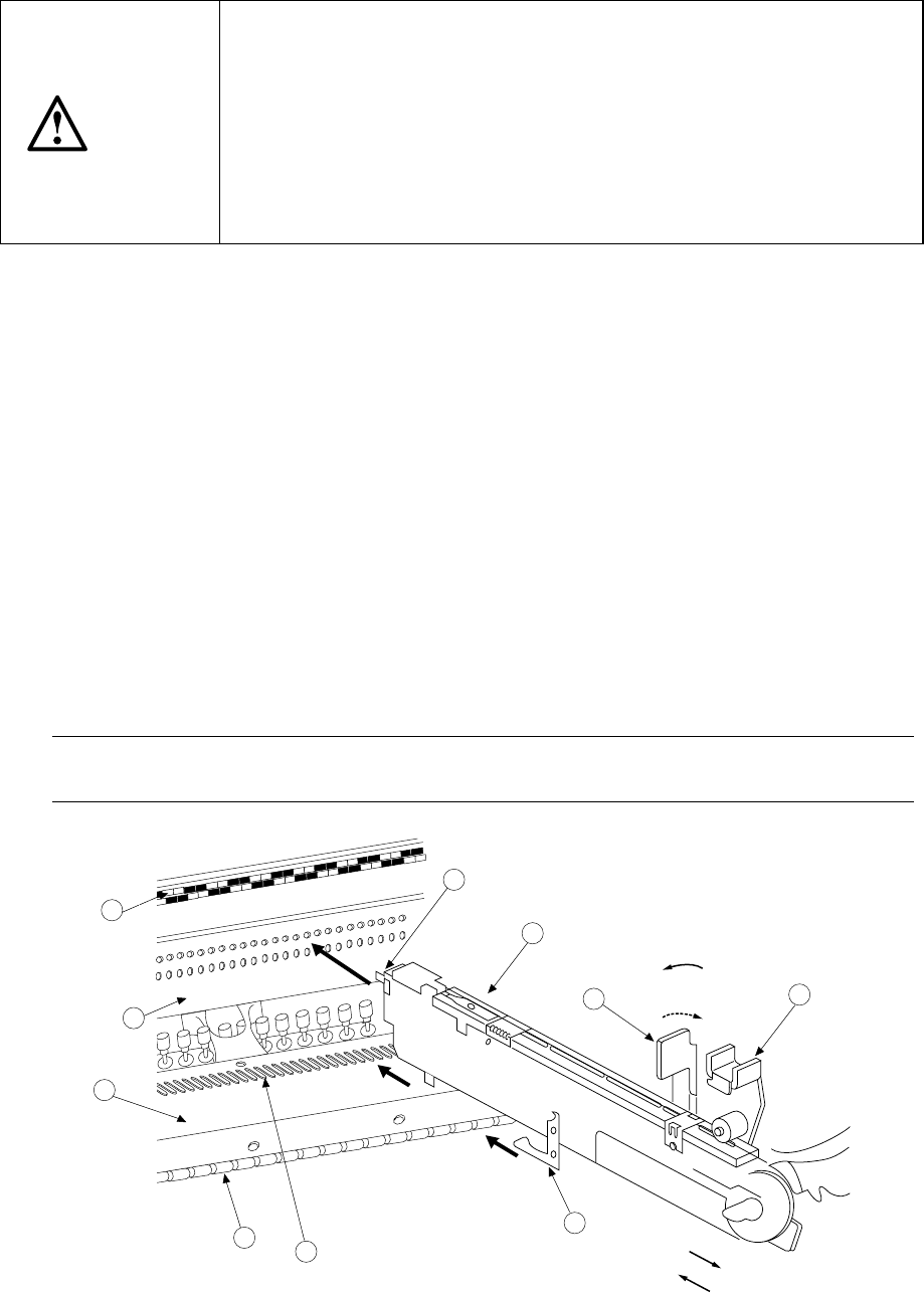
Mounting
1) Place the bottom of the stick feeder ①on the feeder bank ②.
2) Slide the stick feeder ① toward the positioning hole of the fixing plate ③, and
align the guide pin located on the bottom of the stick feeder with the fixing plate B
⑦ as a guide. Fit the positioning pin on the front of the stick feeder into the
positioning hole of the fixing plate ③. To do so, with releasing the toggle clamp
⑩ to align the lock holder ⑨ with the V-shaped groove of the lock shaft ⑧,
push the front of the stick feeder against the fixing plate. Fix the stick feeder
with the toggle clamp ⑩.
In this case, the number of the position label ④ pasted just above the hole into
which the positioning pin on the front of the stick feeder is fit indicates the position
at which the stick feeder is mounted.
Dismounting
1) Release the toggle clamp, then pull back the stick feeder ① straight to remove it.
Note: Be sure to hold the bottom of the stick feeder main unit.
If you hold the upper part of the feeder only, it may damage the spring plate.
5
4
2
3
8
7
1
9
11
10
For detachment
For installation
Fix.
Release.
Figure 12.3.1

12 − 5
12.4 Handling the Feeder Position Indicator (FPI)
The FPI is located at the front of the number label (indicating the feeder mounting
position) for the feeder bank, and equipped with LEDs which correspond to the
number of each number label. These LEDs indicate the feeder mounting position or
component supply condition by lighting or flashing as follows:
Table 12.4.1
Machine condition LED status Function
Flashing Indicates the hole (number) into which the
positioning pin is inserted to position the feeder
specified with the production program
Preparation
Lighting Indicates the range of the feeder bank which the
mounted feeder occupies.
Board production Flashing If the number of the components remaining at a
feeder gets less than the warning level which is
specified as the number of components in the
production program ( this value is set to notify an
operator that the number of the remaining
components is insufficient), the LED
corresponding to the position at which the feeder
is mounted flashes to indicate that the number of
the remaining components is not enough at the
feeder.
Components run-out Lighting If the number of the components remaining at a
feeder which is obtained based on the initial value
specified as the number of components in the
production program reaches "0" during production,
the LED corresponding to the position at which the
feeder is mounted lights to indicate that
components run out at the feeder.
Manually controlled When the feeder
knock pin is set to
ON: Lighting
OFF: Not light
If you use the feeder knock pin control function
which is provided on the Manual control menu to
feed tape or perform the direct knock action, the
LED located at each controlled feeder positioning
pin flashes according to the feeder knock pin
action to indicate which knock pin is controlled.
Note: Unless you enter the number of components to be fed to the feeder or
equivalent correctly at the menu item [Component no. setup] displayed on the
[Change] menu which is invoked from the menu command [Pwb Production],
the number of the remaining components is not displayed correctly and the
indication for component run-out is not displayed properly.
12 − 6
12.5 Handling Bad Mark Sensor
1) Color and size of a bad mark
a) A bad mark on a PC board to which green resist is applied shall be a glossy
white mark of 2.5 mm in diameter or greater.
b) A bad mark on a white ceramic PC board shall be a black mark of 2.5 mm in
diameter or greater.
c) The bad-mark reader cannot recognize the smaller or faded marks. The
bad marks shall be clear and legible.
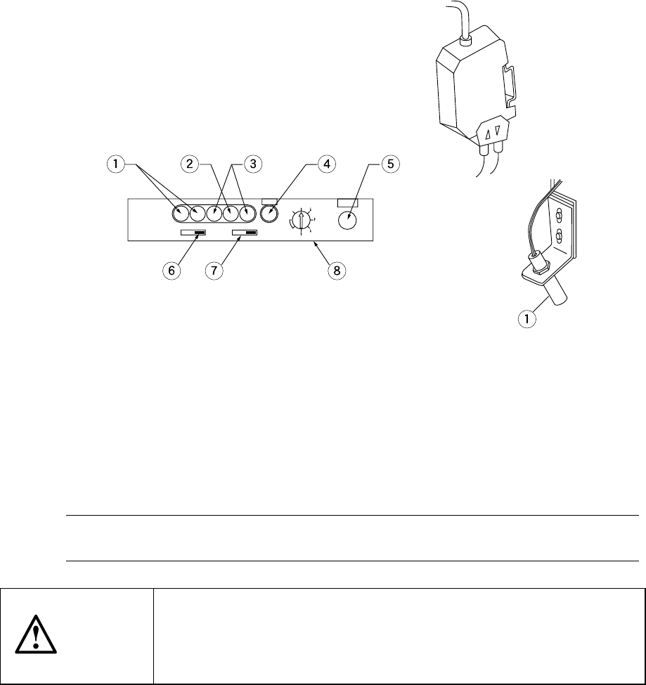
2) Figures 12.5.1 and 12.5.2 show the bad-mark sensor appearance. For details of
installation, see the explanation of the head section.
Figure 12.5.2 Figure 12.5.1
① Light receiving level indicator ⑤ SET button
② Input light indicator ⑥ Output timer switch
③ Spareness indicator ⑦ Output mode switch
④ SET indicator ⑧ Mode switch
3) Adjusting the sensitivity of the bad-mark sensor
Note 1: The software automatically adjusts the sensitivity of the bad mark sensor
(see Section 7.2.2.10 "Bad mark sensor teaching").
CAUTION
The sensitivity adjustment shall be performed only by the authorized
technician who received training for the operation of this machine.
Take care that any person other than the operator does not operate the
machine to prevent accidental activation of the machine.