KE-2030使用说明书.pdf - 第516页
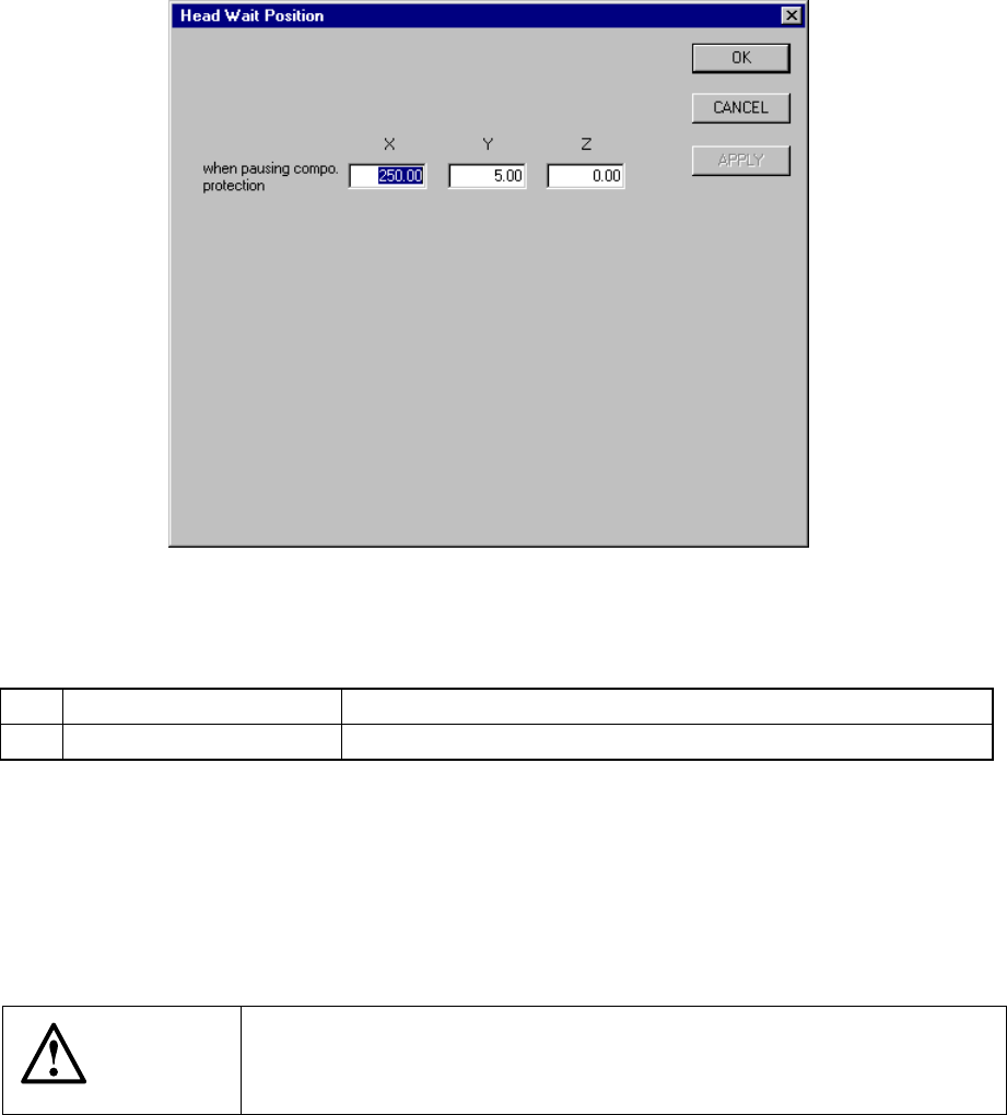
7 − 22 7.2.2.5 Head w ai t posit ion W hen y ou select t he menu item “ Head wait position”, t he following “Head W ait Position” dialog box appears on t he screen as shown below . Figure 7.2.2. 5.1 “Head Wait Position” …
7 − 21
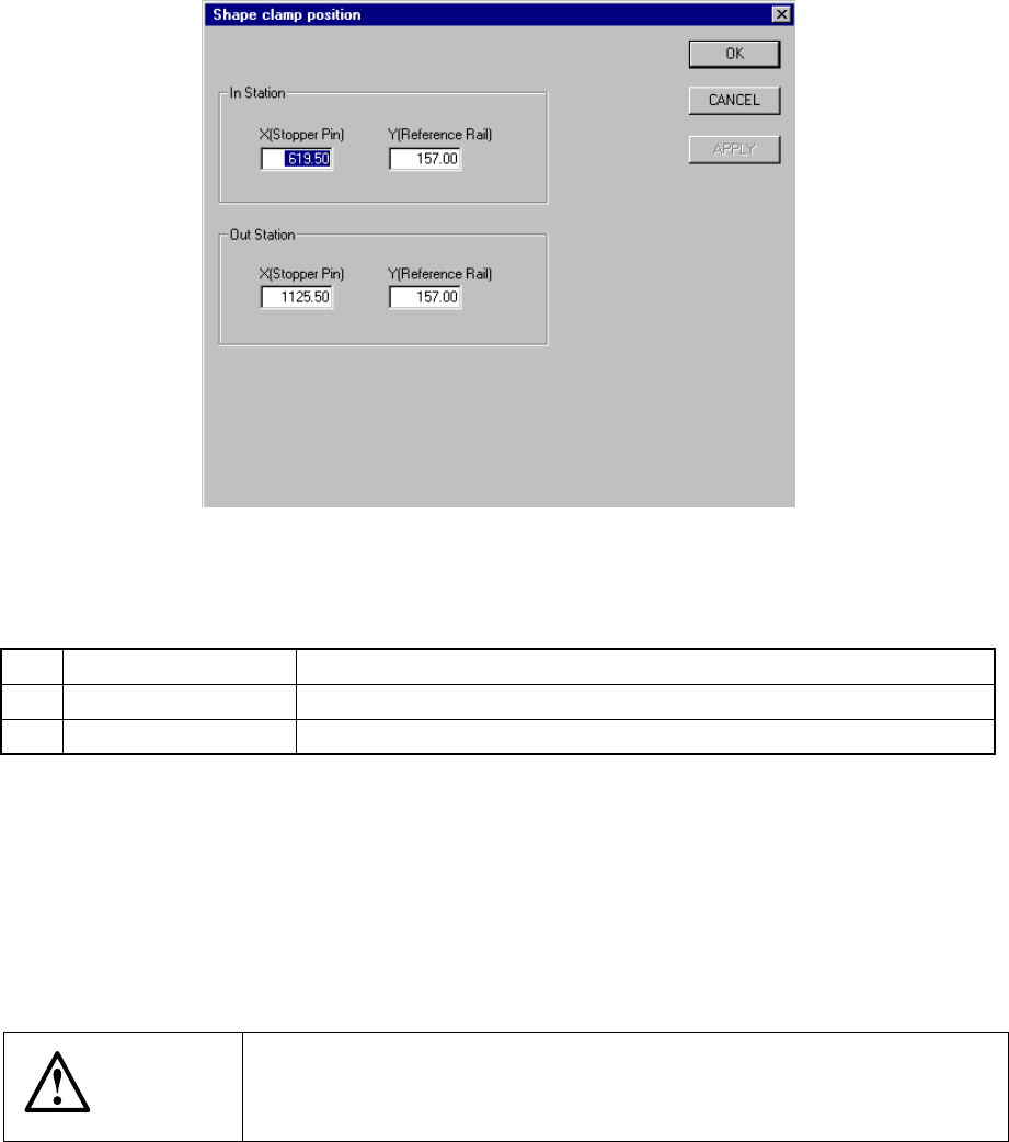
7.2.2.4 Shape clamp position
A screen appears as shown in Figure 7.2.2.4.1 “Shape clamp position setting dialog
box” when [Shape clamp position] is selected from the [Setting Group] menu.
Figure 7.2.2.4.1 Shape clamp position setting dialog box
(1) Setting items
No. Item Description
1 X Stopper pin position
2 Y Reference board transport rail position
(2) Setting the position
− Key in X and Y coordinate value directly from the keyboard.
− Use the HOD to teach and enter the coordinates for X and Y separately. In
this case, if X is in focus, only X is taught, then stored.
− To teach Y, Y shall be in focus.
CAUTION
To avoid a risk of injury, do not place your hand in the machine, nor
move your face or head close to the machine during operation of the
HOD.
7 − 22
7.2.2.5 Head wait position
When you select the menu item “Head wait position”, the following “Head Wait
Position” dialog box appears on the screen as shown below.
Figure 7.2.2.5.1 “Head Wait Position” dialog box
(1) Setting items
No. Item Description
1 X, Y, Z Position at which the head pauses to protect a component
(2) Setting the position
− Key in X, Y, and Z coordinate values directly from the keyboard.
− Use the HOD to teach and enter the coordinates. In this case, if either X or
Y is in focus, both values are taught, then entered.
− Z must be in focus to teach the Z coordinate.
CAUTION
To avoid a risk of injury, do not place your hand in the machine, nor
move your face or head close to the machine during operation of the
HOD.
7 − 23
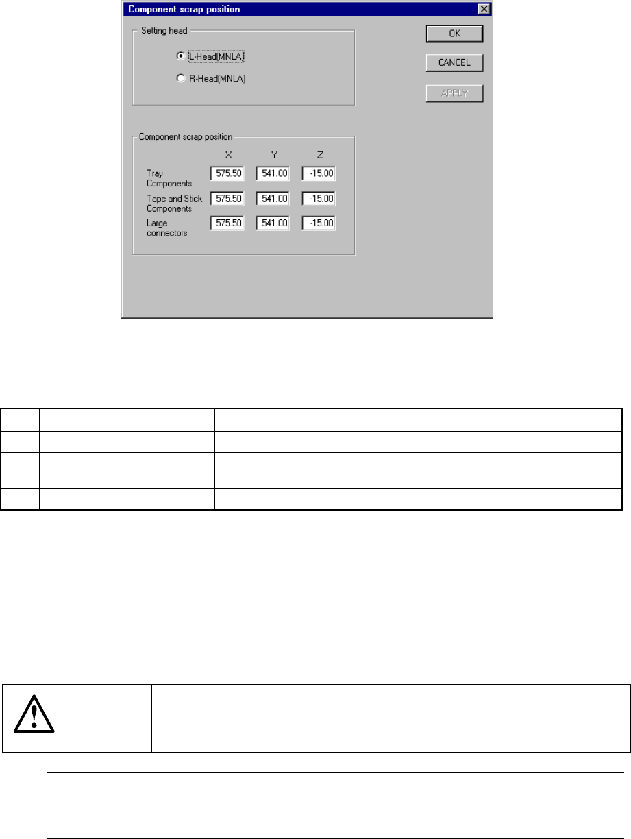
7.2.2.6 Component scrap position
A screen appears as shown in Figure 7.2.2.6.1 “Component scrap position setting
dialog box” when [Component scrap position] is selected from the [Setting Group]
menu.
Figure 7.2.2.6.1 Component scrap position setting dialog box
(1) Setting items
No. Item Description
1 Tray Components (X, Y, Z) The scrap position for IC components
2 Tape & Stick Components
(X, Y, Z)
The scrap position for chip components
3 Large Connectors (X, Y, Z) The scrap position for large components
(2) Setting the position
− Key in X, Y, and Z coordinate values directly from the keyboard.
− Use the HOD to teach and enter the coordinates. In this case, if either X or
Y is in focus bothe values are taught, then entered.
− Z must be in focus to teach the Z coordinate.
CAUTION
To avoid a risk of injury, do not place your hand in the machine, nor
move your face or head close to the machine during operation of the
HOD.
Note: The left head cannot be as the component scrap position on the right side.
The right head cannot be set to the component scrap position on the left side
either.