KE-2030使用说明书.pdf - 第462页
6 − 1 16 6.6 Blank Run W hen y ou select the [ Production conditions] com mand f rom t he menu bar, t hen the [Dry Run] command on t he displayed menu, the "Dry Run conditions" m enu appears on the screen. (1) …
6 − 115
(2) Manual run
When "Manual" is selected in the "Pick tracking" field, the monitoring camera
moves over the first point of pickup after trial run, shoots the picked up component,
outputs it to the monitor screen, and pauses there.
The pause screen for "Manual" is the same as that for "Automatic".
(3) Subjects of pick camera tracking and tracking order
Pickup tracking is performed from No.1 to No.60 at the left front, from No.60 to
No.1 at the left rear, then the right station in this order.
Any pick points used for pick data are subject to tracking operation regardless of
the range of trial run (specified placement points/components).
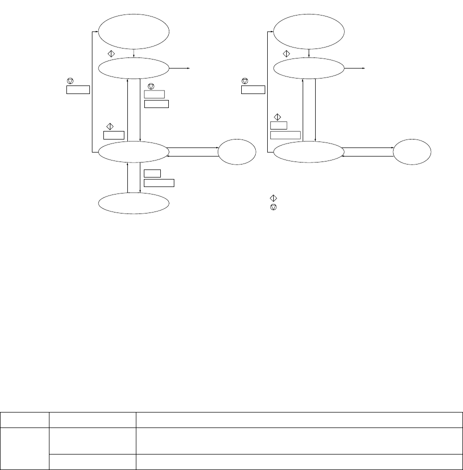
(4) Operation mode
The following chart shows the mode transition in the operation mode.
Condition setting
Continuous operation
Pause
One point tracking
Teaching
Device key of
the HOD
Teaching completed
Movement completed
NEXT
PREVIOUS
q For automatic tracking
CANCEL
PAUSE
CANCEL
PAUSE
One point tracking
Pause Teaching
Device key of
the HOD
Teaching completed
Movement completed
w For manual tracking
CANCEL
NEXT
PREVIOUS
Condition setting
: START switch
: STOP switch
Production
starts.
Production
starts.
- Information of vision camera
The following two types of data are displayed on the vision camera
①
Raw image at pick points
②
Cursor (Crosshair or window cursor)
The size of the window cursor displayed here is the same as the size of
components. For large components which cannot be viewed with the vision
camera or for the components with which the window cursor cannot be used
because their pick angle is not a multiply of 60 degrees, the crosshair cursor
is used instead of the window cursor.
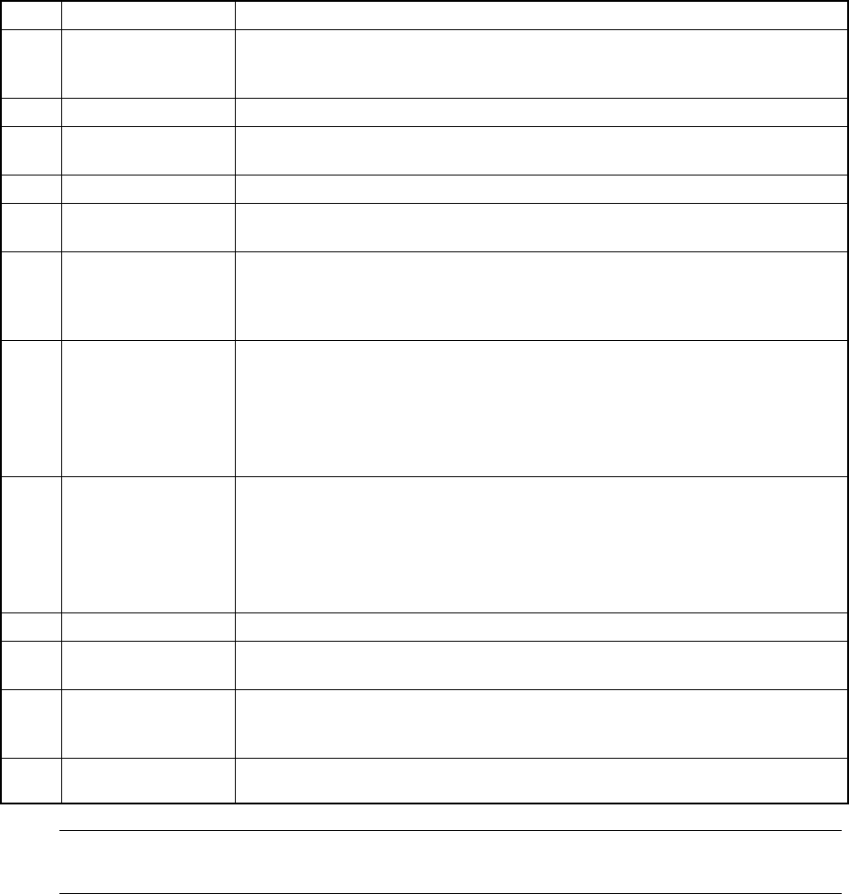
Conditions for displaying information on the vision camera screen
Item Type Conditions
Crosshair cursor For the components whose pick angle is neither 0°, 90°, 180° nor 270°,
or whose dimensions is more than 5.00 mm.
Cursor
Window cursor For the components whose pick angle is 0°, 90°, 180° or 270°.
①
②
6 − 116
6.6 Blank Run
When you select the [Production conditions] command from the menu bar, then the
[Dry Run] command on the displayed menu, the "Dry Run conditions" menu appears
on the screen.
(1) Setting items
No. Item Description
1 Setting items
selection
Switch the dialog box to be displayed on the screen among: Production
conditions dialog box, Trial Run conditions dialog box, and Dry Run conditions
dialog box.
2 Prod. PWB Set the number of boards for blank run.
3 Sequence Select the order of placement sequence: the input order or Opt. (optimized)
order.
4 Exec. mode Select continuous production or step-by-step production.
5 Placement ofs. Designate offset for all placement positions. This offset is added to the
placement positions for actual component placement.
6 Step No. Designate the start line number and the end line number of the range of the
placement data in the input order.
When "Opt. order" is selected as the "Sequence", the start and end line
numbers are handled as the optimized data numbers also.
7 Place tracking After blank run of a board, designate whether or not to perform placement
tracking by the camera. If performed, set whether it is manual or automatic.
Off: Placement tracking is not performed.
Automatic: Placement tracking is performed automatically.
Manual: Stops at each placement position, and then goes to the next
placement position through a key-in by the operator.
8 Pick tracking Before blank run of a board, designate whether or not to perform pickup position
tracking by the camera. If performed, set whether it is manual or automatic.
Off: Pickup tracking is not performed.
Automatic: Pickup tracking is performed automatically.
Manual: Stops at each placement position, and then goes to the next
pickup position through a key-in by the operator.
9 Tracking Station Designate on which unit is to track the blank run operation: left, right or both.
10 Automatic interval When camera tracking is performed automatically, designate the waiting time
duration at a stop position. (time duration in 10 msec: "1" indicates "10 msec")
11 2nd PWB TimeOut Designate the time-out duration which starts production if the IN sensor does
not detect the board transported by the IN station after it is clamped with the
OUT station.
12
Prod. station
(Production station)
Specify a station that is used for producing PWBs: Left, Right or Both.
Note: The value specified on the Operation option menu is displayed at the item
"Reference pin correction", and cannot be changed on this dialog box.
6 − 117
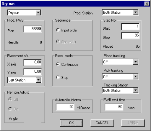
(2) Operation
Figure 6.6.1 shows the Initial dry run conditions menu box.
Figure 6.6.1 Initial Dry run conditions menu box
① Setting items selection
Switches the dialog box to be displayed among: Production conditions
dialog box, Trial Run conditions dialog box, and Dry Run conditions dialog
box.
② Prod. PWB
Enter the predetermined number of PWBs to be produced. The number of
"Result" field is displayed according to setting for the number of produced
boards specified on the Operation Options menu.
③ Sequence
Using the corresponding radio button, select the placement sequence: either
input order or optimized order.
④ Exec. mode
Select either "Continuous" or "Step" execution mode with the corresponding
radio button.
⑤ Placement ofs.
In case a certain production lot has a specific offset (in printing process or in
reference holing process), enter the X and Y offsets in this field. The entered
offset is applied to the entered placement position.
⑥ Step No.
Enter the start line number and end line number to specify the range of
placement. The number of placement points on a board is displayed in the
"Placed" field, and the initial value is displayed in each field. When "Opt.
order" is selected as the "Sequence", you cannot change these initial values.
⑦ Place tracking
Using the radio button, set whether or not to perform placement tracking after