CP-7[732-742]-series Mechanical Reference(2.9E).pdf - 第156页
Part 4 Chapter 1 Station Adjustments Edition 2.4 4-1-6 CP-7 series Mechanical Reference 1.3 W aste T ape Cutter (Station 1) Point The waste tape cutter cuts waste tape that protrudes from feeder tips. A vacuum takes the …
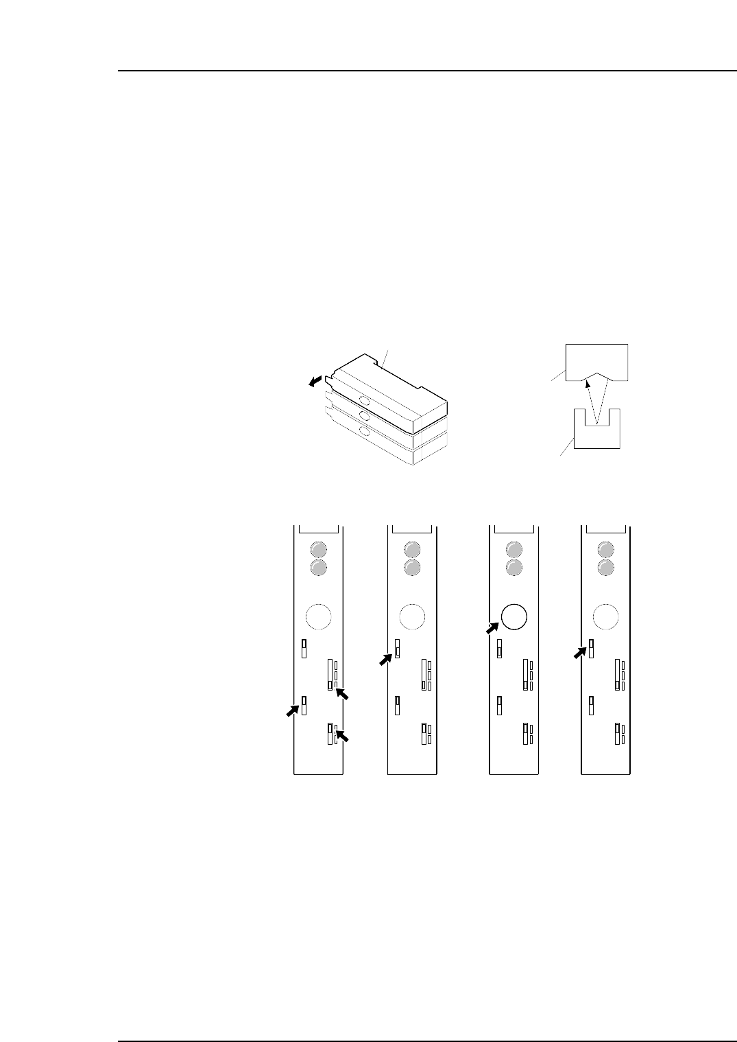
1.2.2 Sensor Amplifier Adjustment
Set the jig (Z9526ADCPJ8550) in position at device number one.
1. Open the cover of the amplifier and set each switch as follows:
Timer: OFF
Output: D ON
Sensitivity: FINE
2. Release the LOCK of the protect switch.
3. At PICK UP POS. D1, check that the light is striking the center of the channel on
the jig as indicated in the figure below. Press and hold down the SET button for
three seconds or more. (The display light changes to yellow.)
4. LOCK the protect switch.
5. Check if the sensor can detect the tape end.
SET
LOCK
OFF D
ON D
OFF
FINE
TURBO
D ON
L ON
SET
LOCK
OFF D
ON D
OFF
FINE
TURBO
D ON
L ON
SET
LOCK
OFF D
ON D
OFF
FINE
TURBO
D ON
L ON
SET
LOCK
OFF D
ON D
OFF
FINE
TURBO
D ON
L ON
( 1 ) ( 2 ) ( 3 ) ( 4 )
C7SM4006a
Tape end check sensor amplifier
Sensor
Jig ( Z9526ADCPJ8550 )
Open the cover
Part 4 Chapter 1 Station Adjustments
Edition 2.4 4-1-5 CP-7 series Mechanical Reference
Part 4 Chapter 1 Station Adjustments
Edition 2.4 4-1-6 CP-7 series Mechanical Reference
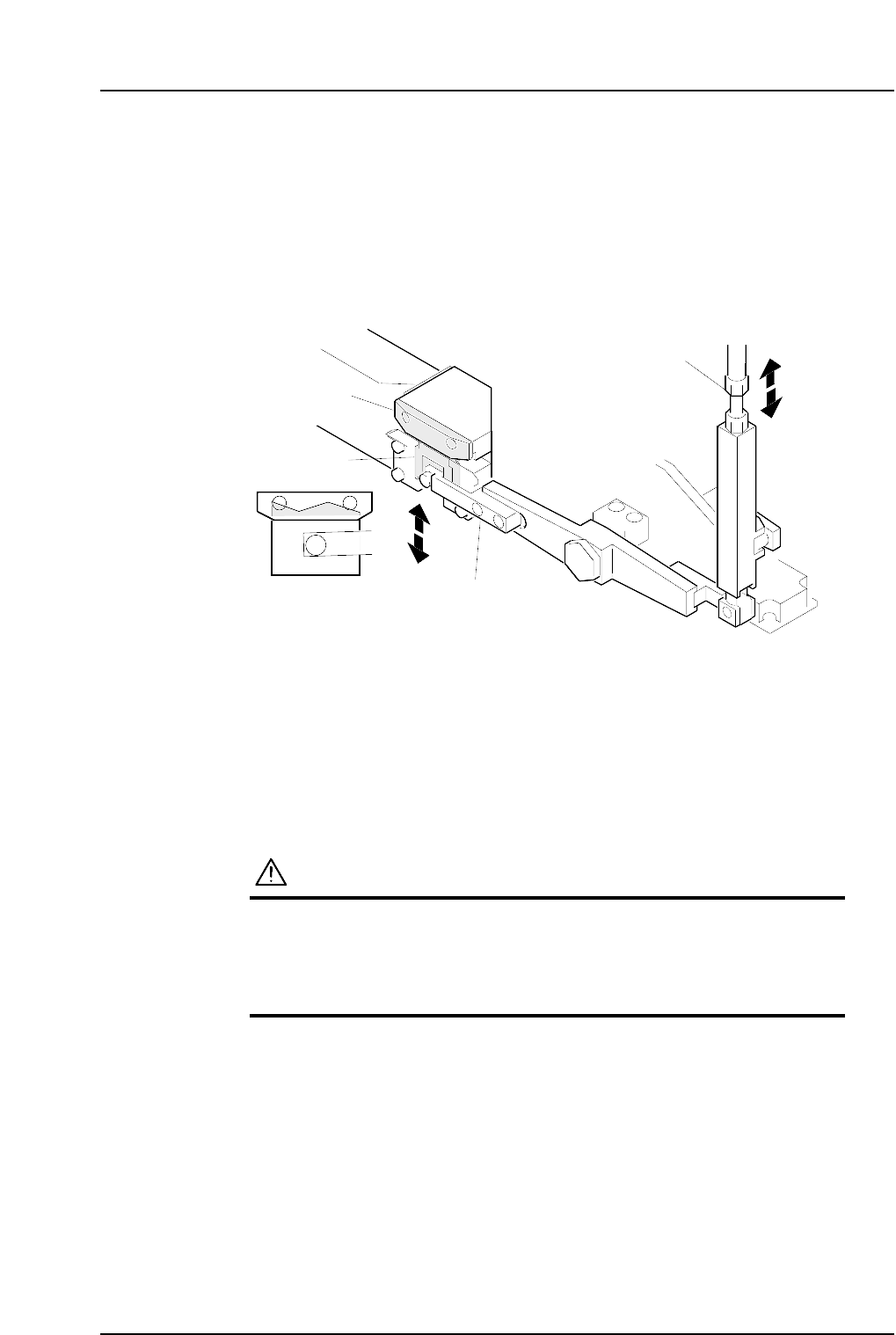
1.3 Waste Tape Cutter (Station 1)
Point
The waste tape cutter cuts waste tape that protrudes from feeder tips. A vacuum takes
the cut tape into the waste tape box at the front side of the machine.
Rotate the adjustment rod to align the movable blade with the fixed blade.
1.3.1 Adjustment Procedure
1. Press the EMERGENCY STOP button. This cuts the 200V servo power and leaves
on only the 100V power supply.
WARNING
• Always be sure to cut off the 200V power before carrying
out any work.
• Exercise extreme caution when working on the machine if
the cam is not at its origin (0 deg.). Recoil of the cam
axis can endanger the operator.
2. Use the cam handle to rotate the cam to 0°.
Adjustment rod
Fixed cutter
Movable cutter
Cutter lever
C7SM4007a
Part 4 Chapter 1 Station Adjustments
Edition 2.4 4-1-7 CP-7 series Mechanical Reference
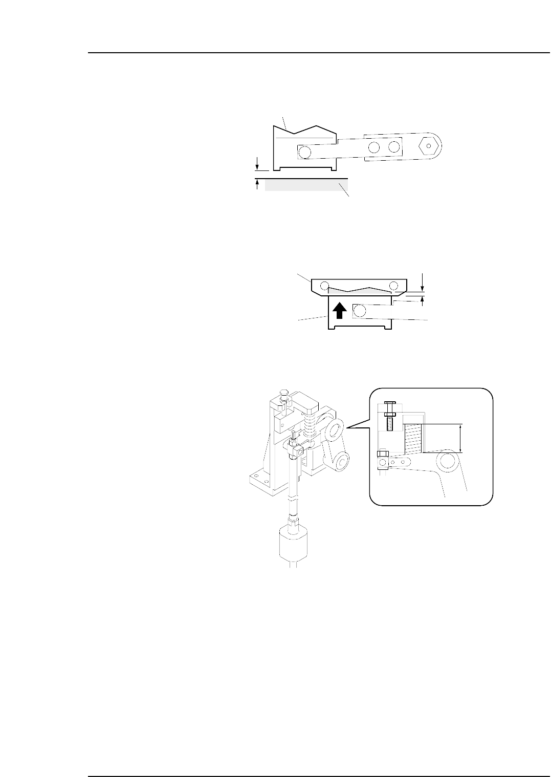
3. Ensure that there is a gap of 0 ~ 0.5 mm between the movable cutter lower surface
and the cutter unit base.
4. Use the cam handle to rotate the cam to 194°.
5. Adjust the rod so that the movable blade and fixed blade engages by 0.5 to 1.0
mm.
6. Ensure that the spring length is 38 mm.
C7SM4010b
38 mm
Fixed cutter
Movable cutter
0.5~1.0 mm
C7SM4008a
0~0.5 mm
C7SM4009b
Movable cutter
Cutter plate