CP-7[732-742]-series Mechanical Reference(2.9E).pdf - 第191页
1. Press the EMERGENCY STOP button to take the 200V down to 100V. W ARNING • Always be sure to cut off the 200V power before carrying out any work. • Exercise extreme caution when working on the machine if the cam is not…
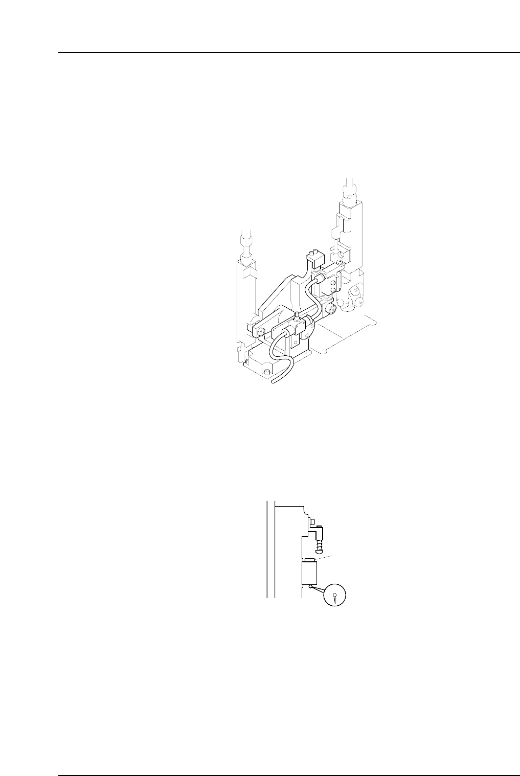
1.13 Mechanical Valve Switching (Station 13)
Point
The station 13 mechanical valve is used to switch the vacuum off inside the nozzle. This
releases the negative pressure in the nozzle, and the nozzle can no longer hold a part.
Verify that parts which fail vision processing are discarded at station 13.
1.13.1 Valve Switching Unit Position Adjustment
This adjustment should be performed on the high valve head after completing adjustments to
the vertical movement of the nozzle during the placement (Refer to 1. 10 “Nozzle Vertical
Movement During Placement” for details). The high valve head can be identified by its
height. The heights of the spool lower surface are measured for all placing heads with spools
lifted, and the highest one is referred to as the high valve head.
Spool
C7SM4055
C7SM4041a
Part 4 Chapter 1 Station Adjustments
Edition 2.4 4-1-40 CP-7 series Mechanical Reference
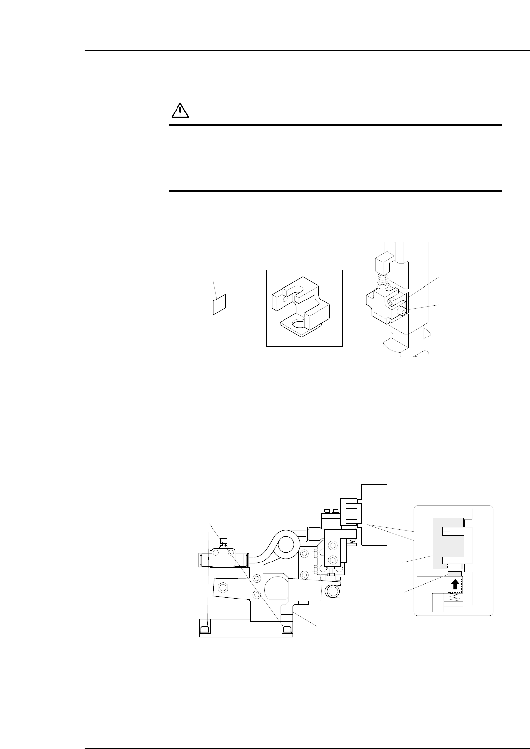
1. Press the EMERGENCY STOP button to take the 200V down to 100V.
WARNING
• Always be sure to cut off the 200V power before carrying
out any work.
• Exercise extreme caution when working on the machine if
the cam is not at its origin (0 deg.). Recoil of the cam
axis can endanger the operator.
2. Use an inching operation and move the high valve head to 12 station.
3. Attach the centering jig to the mechanical valve of the high valve head.
Note: Put the 0.2 mm spacer between the fixing bolt and the mechanical valve in order to
avoid any scratch to the mechanical valve.
4. Move the high valve head to station 13.
5. Use the cam handle to rotate the cam to the following cam angles:
CP-732E : 194°
CP-742ME/CP-742E : 190°
Make sure that the pusher is inserted smoothly to the hole at the bottom of the
centering jig. If not, loosen the fixing bolts and adjust the position of the valve
switching unit.
C7SM4067
Centering jig
Pusher
Fixing bolt
Valve switching unit
Z9627DGPJ0110
t = 0.2 mm
Centering jig
Spacer
Bolt
Mechanical valve
Part 4 Chapter 1 Station Adjustments
Edition 2.4 4-1-41 CP-7 series Mechanical Reference
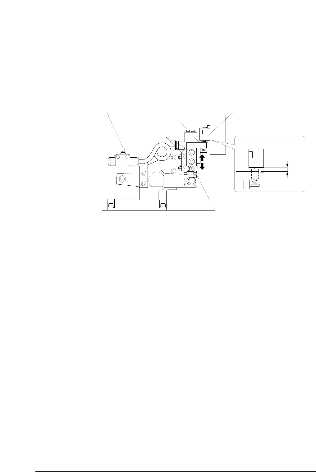
6. Return the cam to 0°, and then detach the centering jig from the mechanical valve.
7. Use the cam handle to rotate the cam to the following cam angles:
CP-732E : 194°
CP-742ME/CP-742E : 190°
Loosen the fixing bolts, then adjust the height of the valve switching unit by
turning the height adjustment bolt so that the gap between the bottom of the
mechanical valve and the top surface of the pusher bracket becomes 1.7 mm.
Note: Do not touch the speed regulator.
The blow air pressure is set to 7.0 ± 0.5 kPa (9st: 15.0 ± 0.5 kPa). The user should
not change the setting, as a manometer is required for the adjustment.
C7SM4042b
Fixing bolt
Speed regulator
Pusher bracket
Mechanical valve
Adjustment bolt
1.7 mm
Part 4 Chapter 1 Station Adjustments
Edition 2.4 4-1-42 CP-7 series Mechanical Reference