CP-7[732-742]-series Mechanical Reference(2.9E).pdf - 第37页
[Stations 1-16] Stations 1-16 represent the positions of the 16 placing heads. In this manual, “Station” is abbreviated as “St”. The functions of each of the 16 stations are explained below. St1: Picks up parts from the …
2 Functions of Each Part
Parts Mounting System
Cam box
The cam box system comprises a cam axis motor, index units, cam axes, cam levers, and
air cylinders.
Index units
Two index units are housed in the cam box. One is used to index the nozzle shaft clutch,
and the other is used to index the nozzle holder.
Placing heads
There a total of 16 placing heads mounted around a single rotary head. The placing
heads comprise nozzles, shafts, and holders. Each placing head is fitted with six nozzle
types, with the appropriate nozzle being selected in accordance with the size of the part
which is to be placed. Placing heads pick up parts from the feeder, hold the parts during
vision processing, and then place the parts on a panel.
C7SM1020a
Cam box
Index units
Placing heads
Stations 1-16
Feeders
Tape cutter
Pallet supply device
PCU (Pallet Change Unit)
Parts camera
Mark camera
Carrier loader
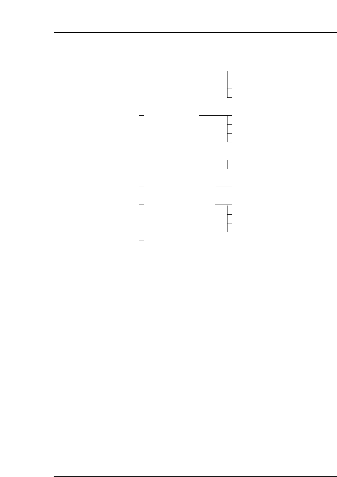
CP-7-series machines
Part placement system
Part supply system
Vision system
Panel conveyance system
Electrical control system
Pneumatic control system
Machine functions
Operation panel
Control box
Servo box (Servo BKT)
UPS (Uninterrupted Power Supply Unit)
Part 1 Chapter 2 Functions of Each Part
Edition 2.4 1-2-1 CP-7 series Mechanical Reference

[Stations 1-16]
Stations 1-16 represent the positions of the 16 placing heads. In this manual, “Station” is
abbreviated as “St”. The functions of each of the 16 stations are explained below.
St1: Picks up parts from the feeder, performs feeder indexing, and detects the
end of the parts tape.
St2: Checks for the presence of large sized parts. Also performs pre-rotation
(PQ) operations. The pre-rotation function rotates parts in advance to the a
position near the placement angle specified in the placement program. Pre-
rotation occurs in 90-degree increments.
St3: Fine-adjusts the nozzle’s origin position.
St5: Two CCD cameras (Wide View and Narrow View) check the presence and
pick-up condition of the parts.
St6: Measures the height of parts which the nozzle has picked up (option).
Also,measures the length of the nozzles (option).
St8: Performs fine-rotation (FQ) operations. Rotates a part to its final placement
angle based on the vision processing results at St5.
St9: Places parts on the panels being produced. Parts rejected during vision
processing at St5 are not placed.
St10: Performs reverse pre-theta (PQ) and fine-theta (FQ) rotation operations.
Also checks the nozzle’s origin position.
St11: Verifies that nozzles lowered for part placement have been raised again,
and checks the nozzle “Holder A” position for the production log.
St13: Rejects parts deemed defective by the vision check at St5. Also checks the
positions of the 6 nozzles before nozzle changes.
St14: Performs (by servo motor operation) nozzle changes for the 6 nozzles.
St15: Checks the positions of the 6 nozzles after nozzle changes.
Parts Supply System
Feeders
The feeders supply taped parts to St1 where they are picked up. As a rule, CP-7-series
machines can use CP-6-series feeders, however a special CP-7-series reel holder may be
required for certain reel sizes.
Tape cutter
The tape cutter is located beneath St1 of the placing head, and consists of upper and
lower cutters which cut the waste tape fed from the feeder. The cut waste tape is then
carried through a vacuum duct to the waste tape box at the bottom of the machine.
Part 1 Chapter 2 Functions of Each Part
Edition 2.4 1-2-2 CP-7 series Mechanical Reference

Pallet supply device
The feeders are set on two pallets, one for each of the device tables. The pallet supply
devices comprise a servo motor and a ballscrew, and move to positon the required parts
at the pick-up position.
PCU (Pallet Change Unit)
The PCU allows the operator to perform pallet changeover.
Vision System
Parts camera
This CCD camera checks the size and shape of picked up parts.
Mark camera
A mark camera comprises a CCD camera, a light, and a mounting bracket. After the
CCD camera reads the fiducial marks on the panels being produced, the coordinates are
automatically corrected (offset) in accordance with internal calculations.
Panel Conveyance System
Carrier loader
The machine’s sequencer loader conveys panels between the in-conveyor, the XY-table,
and the out-conveyor, by way of panel clamp units (carriers). The in and out-carriers are
both operated by air cylinders in accordance with the placing program.
In-conveyor: Conveys the panel into the machine and transfers it to the in-carrier by
means of the in-lifter.
In-carrier: Transfers the panel from the in-conveyor to the XY-table.
XY-table: Clamps the panel in position and moves it to and from the position for
placement.
Out-carrier: Transfers the panel from the XY-table to the out-conveyor.
Out-conveyor: Conveys the panel to the next machine in the line.
Electrical Control System
Operation panel
The operation panel comprises switches and a touch screen monitor which are used to
operate the machine.
Control box
The control box contains electrical circuit boards used to control the machine. It is also
equipped with a CD ROM drive which is required to install software.
Servo box (Servo BKT)
The servo box contains the servo BKT to which the servo amplifiers and boards are
attached. Users should not interfere with this box, except to perform servo amplifier
replacement.
Part 1 Chapter 2 Functions of Each Part
Edition 2.4 1-2-3 CP-7 series Mechanical Reference