CP-7[732-742]-series Mechanical Reference(2.9E).pdf - 第174页
1.7.2 Sensor Amp Adjustment Open the front cover and follow the procedures below. 1. Check that the output dip switch is set to "L ON". 2. Set the power modes and timer modes as detailed below. 2-1. Press and h…
1.7 Large Parts Check Sensor (Station 2)
Point
The machine has a sensor at station 2 that checks for large parts (1 mm or larger in
height). The machine stops immediately if no part is detected.
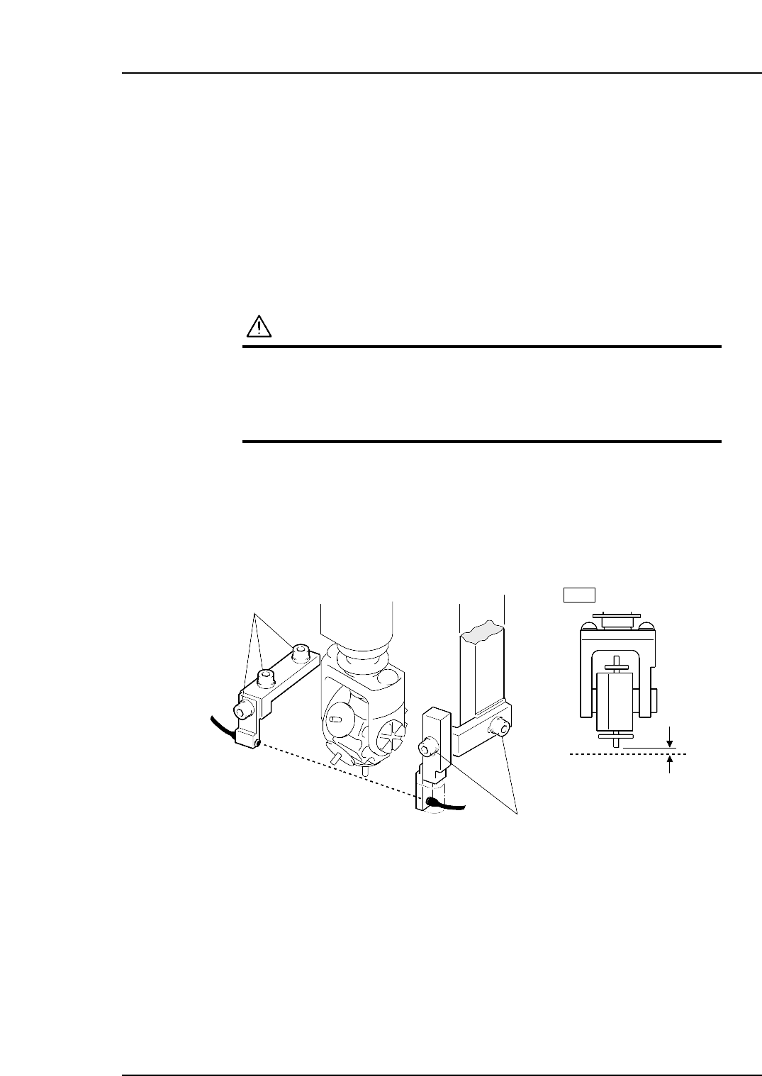
1.7.1 Sensor Position Adjustment
1. Press the EMERGENCY STOP button. This cuts the 200V servo power and leaves
on only the 100V power supply.
WARNING
• Always be sure to cut off the 200V power before carrying
out any work.
• Exercise extreme caution when working on the machine if
the cam is not at its origin (0 deg.). Recoil of the cam
axis can endanger the operator.
2. Use the cam handle to rotate the cam to 200°.
3. Adjust the sensor bracket positions so that the sensor beam goes through 0.7 ~ 0.8
mm below the nozzle tip. Use a thickness gauge etc. to ensure the sensor reaction
while working.
4. Actually pick up a large part to check the sensor reaction.
0.7~0.8 mm
Adjustment bolts
Adjustment bolts
2st
Light beam
Light beam
C7SM4024a
Part 4 Chapter 1 Station Adjustments
Edition 2.4 4-1-23 CP-7 series Mechanical Reference
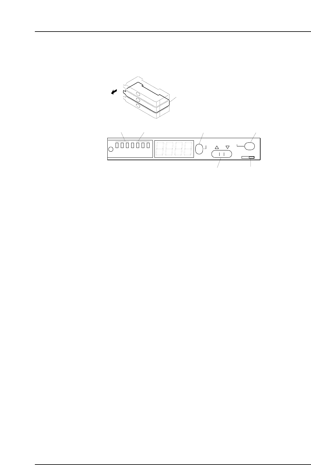
1.7.2 Sensor Amp Adjustment
Open the front cover and follow the procedures below.
1. Check that the output dip switch is set to "L ON".
2. Set the power modes and timer modes as detailed below.
2-1. Press and hold down the MODE button for three seconds or more to change
the display to "turb".
Use the up and down arrow buttons to set the power mode to "SUPER".
2-2. Press the MODE button to change the display to "dLy".
Use the up and down arrow buttons to set the timer mode to OFF.
2-3. Press the MODE button again to return the display to the original state.
3. Press the MODE button to toggle the display from the light value, to the
percentage value (value + "P"), and then back to the light value.
Ensure that the figures for all the sensors are above the minimum values shown
below.
200 digit (target: 500 digit)
Note: The sensor should be replaced when the light reading is at approximately 4095.
Check the following items if the light reading does not reach the minimum
required value.
a The position of the sensor bracket.
b Check that the sensor is correctly attached to the sensor bracket.
c The positioning of the fiber and attachment tips.
d Check whether the fiber and amp connections are correctly inserted.
e Check the condition of the fiber wiring.
4. Change the display to show the percentage value by pressing the mode button to
toggle the display as required.
5. Use the up and down arrow buttons to set the value to 200.
Note: The arrow buttons cannot be used if the display reads 999P. In this situation, press
the SET button twice to revert the display to 100P.
Large parts check sensor amplifier
Open the cover
SET
SUPER
TURBO
FINE
SET
40ms
10ms
OFF
MODE
D ON L ON
C7SM4025a
Output dip switch
[MODE] button[SET] buttonPower mode Timer mode
[ ▼
•
▲ ]
button
Part 4 Chapter 1 Station Adjustments
Edition 2.4 4-1-24 CP-7 series Mechanical Reference
1.8 Pre-theta Movement (Station 2)
Point
Pre-theta rotates the nozzles with parts picked up at station 1 by 90°, 180° or -90°
depending on the settings in the production program.
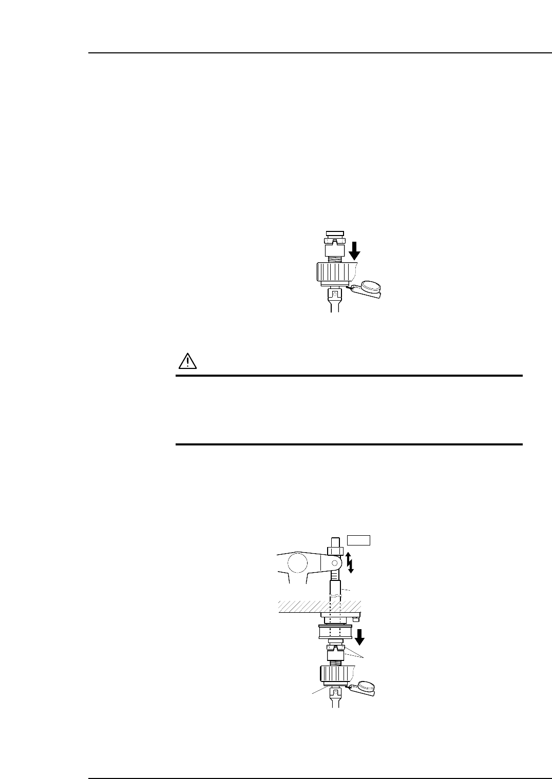
1.8.1 Clutch Meshing Check
Perform this check on the low-pressure nozzle.
Note: The low-pressure nozzle refers to the placing head (out of the 16) that receives the weakest
pushing pressure. Use the low-pressure nozzle for meshing checks at stations 2, 8 and 10.
1. Press the EMERGENCY STOP button to take the 200V down to 100V.
WARNING
• Always be sure to cut off the 200V power before carrying
out any work.
• Exercise extreme caution when working on the machine if
the cam is not at its origin (0 deg.). Recoil of the cam
axis can endanger the operator.
2. Set the dial gauge to the bottom of the nozzle shaft brake.
3. Use the cam handle to rotate the cam to 200°.
4. Ensure that the clutches mesh properly and the placing head assembly deflects the
dial gauge by 0.30 ~ 0.35 mm as illustrated below.
Clutch
Nozzle shaft brake
2st
Rod
Measure the amount
of push down
0.30~0.35 mm
C7SM4027a
Measure the pushing pressure
at all nozzles to determine the
lowest value.
C7SM4058
Part 4 Chapter 1 Station Adjustments
Edition 2.4 4-1-25 CP-7 series Mechanical Reference