CP-7[732-742]-series Mechanical Reference(2.9E).pdf - 第200页
1.16 Nozzle Detection Sensor (Station 15) Point Station 15 uses three nozzle detection sensors to detect which of the six nozzles (No. 1 ~ 6) was selected during nozzle selection at station 14. The adjustments are the sa…
1.15.2 Nozzle Change Stroke Adjustment
1. Press the EMERGENCY STOP button to take the 200V down to 100V.
WARNING
• Always be sure to cut off the 200V power before carrying
out any work.
• Exercise extreme caution when working on the machine if
the cam is not at its origin (0 deg.). Recoil of the cam
axis can endanger the operator.
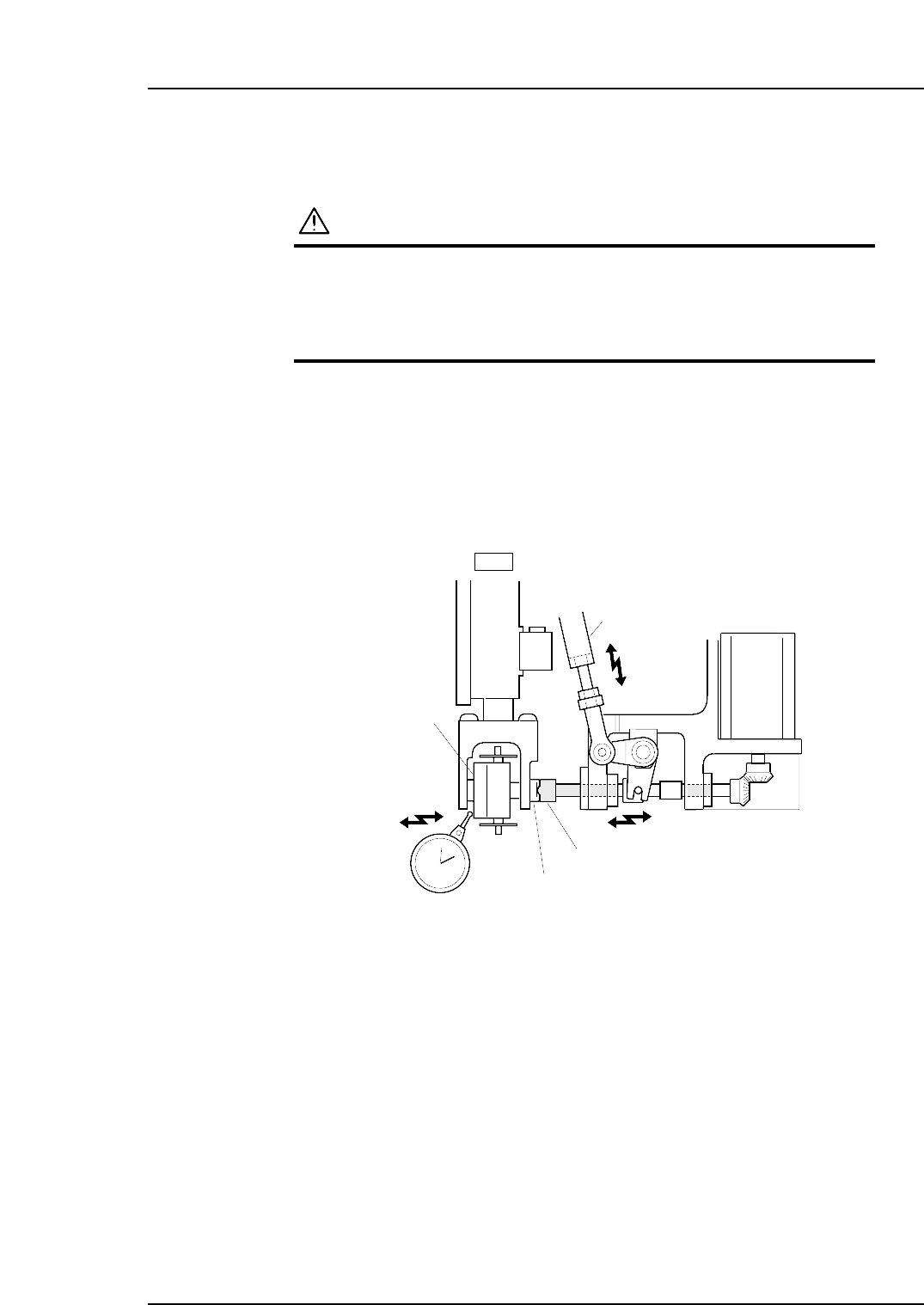
2. Position the cam at an angle of 0° and turn the station 14 solenoid to ON (Y037
ST14 NOZZLE CHANGE SOL ENGAGED) to activate the cam lever.
3. Use the cam handle to rotate the cam to 141°.
4. Verify that the nozzle change clutch is engaged with the holder clutch, and that
the rotary holder is pushed 0.01 to 0.05 mm as shown in the figure below.
5. If the push amount is outside this range, adjust by turning the adjusting rod.
Nozzle change clutch
Holder clutch
Adjustment rod
Rotary holder
14st
0.01
~
0.05 mm
C7SM4048
Part 4 Chapter 1 Station Adjustments
Edition 2.4 4-1-49 CP-7 series Mechanical Reference
1.16 Nozzle Detection Sensor (Station 15)
Point
Station 15 uses three nozzle detection sensors to detect which of the six nozzles (No. 1 ~ 6)
was selected during nozzle selection at station 14.
The adjustments are the same as for station 13 nozzle detection sensor.
1.16.1 Sensor Position Adjustment
1. Press the EMERGENCY STOP button to take the 200V down to 100V.
WARNING
• Always be sure to cut off the 200V power before carrying
out any work.
• Exercise extreme caution when working on the machine if
the cam is not at its origin (0 deg.). Recoil of the cam
axis can endanger the operator.
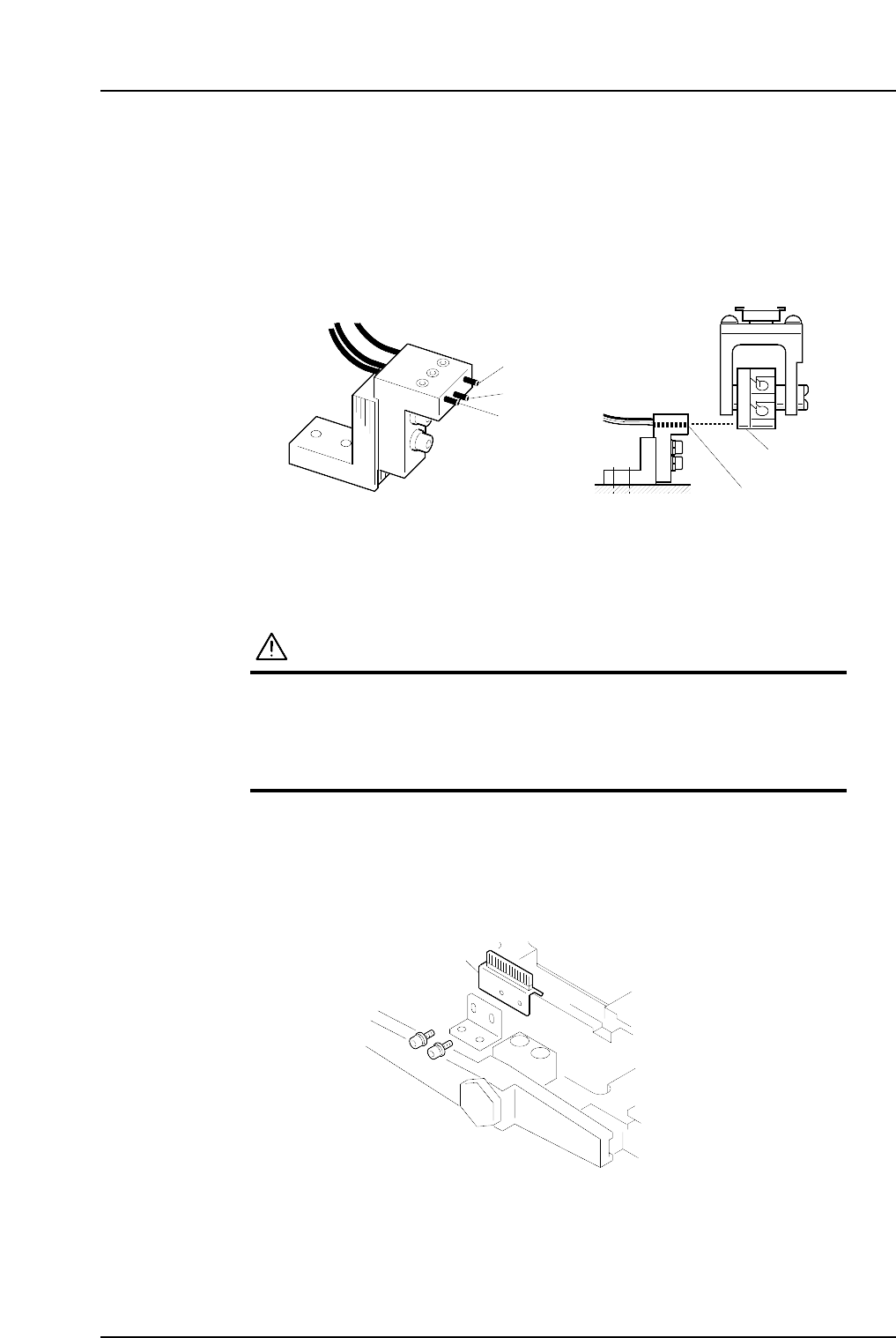
2. Remove the nozzle holders of the reference head and the neighboring heads.
3. Use an inching operation and move the reference head to 13 station.
4. Use the cam handle to rotate the cam to 200°.
5. Detach the reject parts brush.
C7SM4059a
Reject parts brush
Dog
Sensor 3
Sensor
Sensor 2
Sensor 1
C7SM4043b
Part 4 Chapter 1 Station Adjustments
Edition 2.4 4-1-50 CP-7 series Mechanical Reference
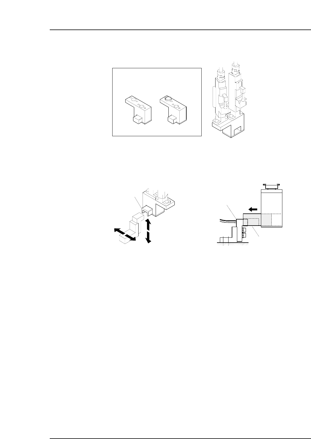
6. Attach the adjustment jig (for station 15) to the placing heads at stations 15 and 16.
Note: Do not turn the cam with the jig attached to the placing heads; otherwise the heads
might be damaged.
7. Adjust the sensor bracket position so that it can be smoothly inserted to the cavity
of the jig block.
Jig block
Jig block
Sensor bracket
C7SM4061
C7SM4062
ADCPJ8030 (CP-732E)
ADGPJ8050 (CP-742ME,CP-742E)
15 st
16 st
For ST13For ST15
Adjustment jig
Part 4 Chapter 1 Station Adjustments
Edition 2.4 4-1-51 CP-7 series Mechanical Reference