CP-7[732-742]-series Mechanical Reference(2.9E).pdf - 第179页
6. Adjust the rod. • CP-732E Adjust the rod so that there is ± 0.02 mm difference between the slider groove and the cam groove. • CP-742ME/CP-742E Adjust the length of the rod using the bolt to ensure that the distance b…
Caution: Do not disassemble the placing head assembly carelessly. Special equipment and
skills are required to perform the reassembly of the placing head. Such procedures
should be attempted only by users who have attended training at Fuji and are
equipped with the necessary tools, or whilst under the direct guidance of a
serviceman.
4. Move the area for the removed placing head to station 9 (0°), then turn on the
solenoid (Y035 ST9 PLACE SOL ENGAGED).
5. Set the cam angle to 0°, and position the dial gauge as shown in the figure below.
Note: The dial gauge setting position differs for the CP-733E and CP-743ME/CP-743E.
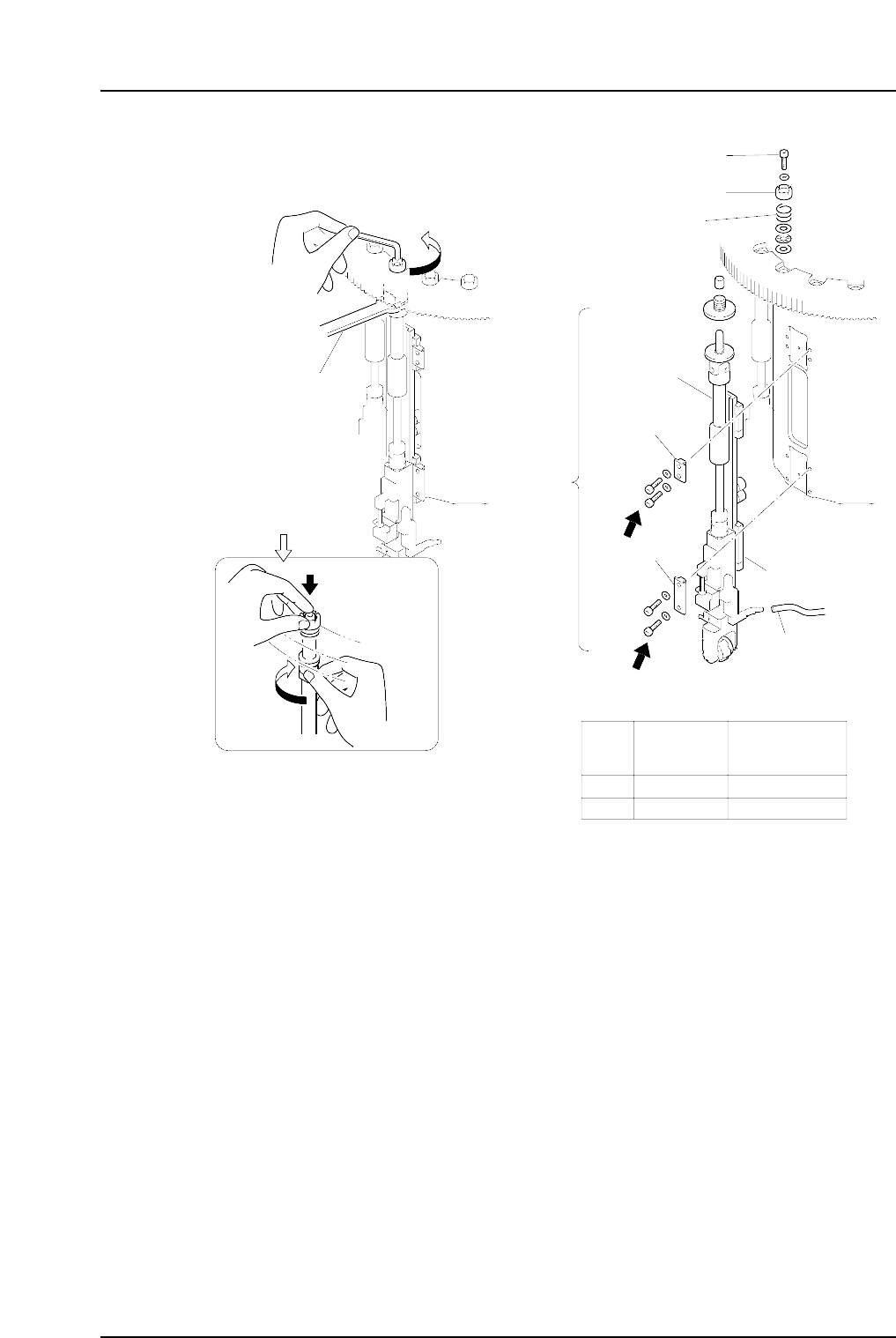
Outer
shaft
Clamper
Spanner
( DCPJ0450 )
Clutch
Bolt
Spring
Linear guide
Vaccum hose
A
B
Part
Bolt
size
Torque
Nm ( Kgf•cm )
A
B
M4
M4
2 ( 20 )
2 ( 20 )
Clamper
C7SM4012a
Nozzle
shaft
assembly
Caution : Washers may jump when the
bolt is loosened because of the
spring under the clutch.
Rotate the placing
head while holding
the bolt with your
finger.
Part 4 Chapter 1 Station Adjustments
Edition 2.4 4-1-28 CP-7 series Mechanical Reference
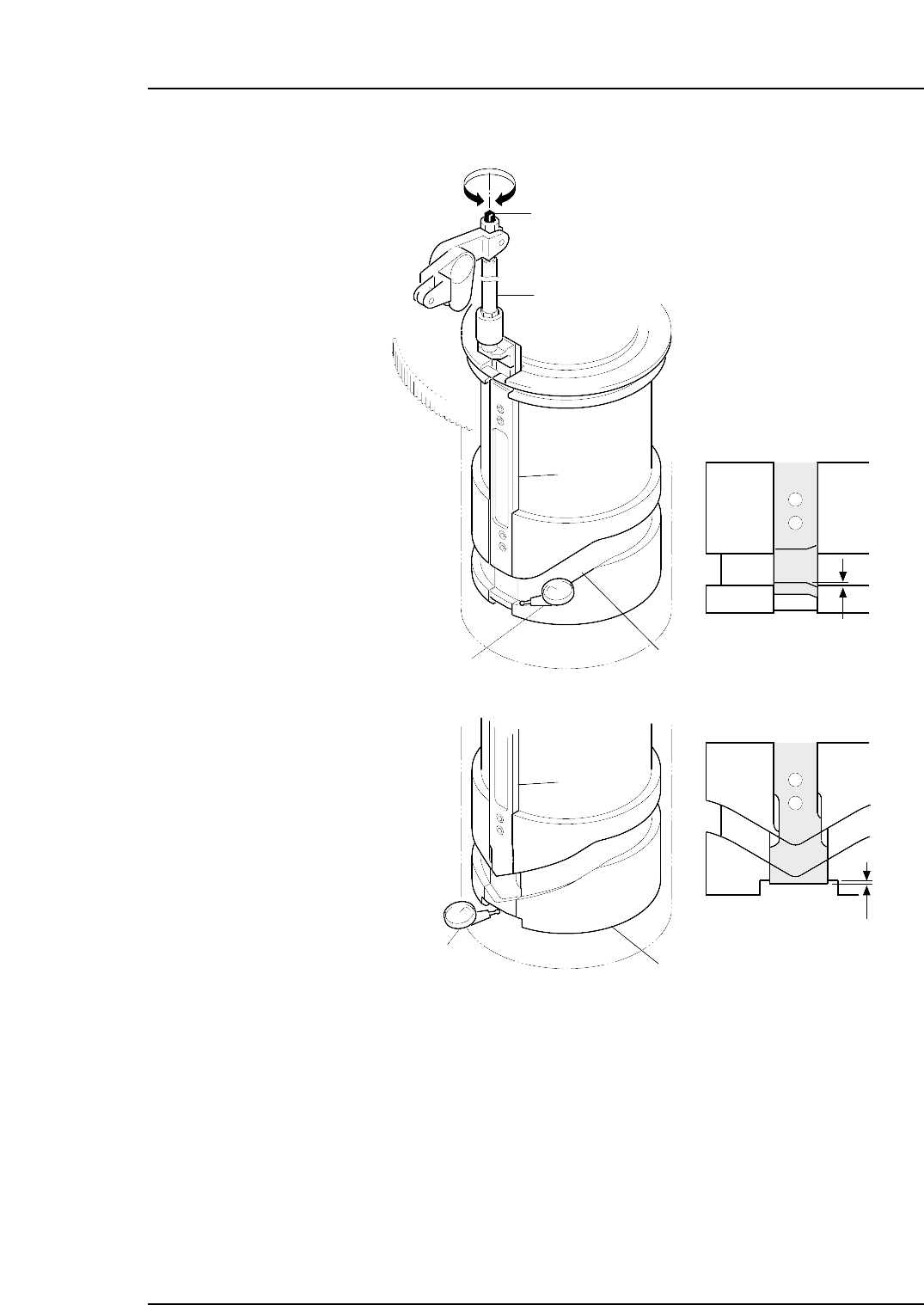
6. Adjust the rod.
• CP-732E
Adjust the rod so that there is ±0.02 mm difference between the slider groove
and the cam groove.
• CP-742ME/CP-742E
Adjust the length of the rod using the bolt to ensure that the distance between
the base of the slider and the cut out section in the cylindrical cam is within the
range of ±0.02 mm.
7. Reattach the placing head assembly in the original location.
Using the clutch alignment jig, reverse the removal procedures to attach the
assembly.
Slider
Cam groove
Slider
Cylindrical cam
Rod
Adjustment bolt
–0.02 mm
–0.02 mm
C7SM4028a
Dial gauge
Dial gauge
<CP-732E>
<CP-742ME/
CP-742E>
Part 4 Chapter 1 Station Adjustments
Edition 2.4 4-1-29 CP-7 series Mechanical Reference
1.10.2 Adjusting the Nozzle UP Limit Sensors
The nozzle UP limit sensor which detects the up limit position of the nozzle UP/DOWN
rod at station 9 is mounted inside the cam box. Adjust the mounting position of this
sensor so that it switches ON when the nozzle is at its UP limit position.
1. Press the EMERGENCY STOP button to take the 200V down to 100V.
WARNING
• Always be sure to cut off the 200V power before carrying
out any work.
• Exercise extreme caution when working on the machine if
the cam is not at its origin (0 deg.). Recoil of the cam
axis can endanger the operator.
2. Set the cam axis at the 0-degree position.
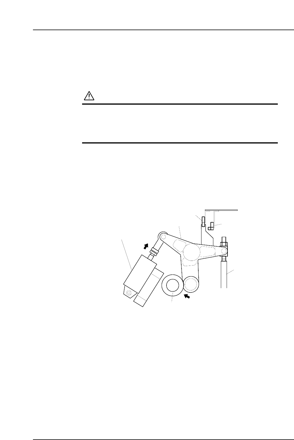
3. Activate the ST9 placing solenoid air cylinder (located in the cam box):
Execute the following I/O commands: [Maintenance] - [I/O Check] - [Standard I/O]
- [Y035 ST9 PLACE SOL ENGAGED] - [Output Signal ON]
The cam lever will then follow the cam axis.
9ST Place solenoid
air cylinder
Cam lever
Nozzle UP/DOWN rod
Cam axis
Cam lever follows
the cam axis.
C7SM4029a
Nozzle up limit sensor
Nozzle down limit sensor
Part 4 Chapter 1 Station Adjustments
Edition 2.4 4-1-30 CP-7 series Mechanical Reference