CP-7[732-742]-series Mechanical Reference(2.9E).pdf - 第212页
Part 5 Chapter 1 Troubleshooting T able Edition 2.7 5-1-9 CP-7 series Mechanical Reference No. 4-16 4-17 M: Part 1 Chapt 3 M: Part 1 Chapt 3 S: Part 3 Chapt 1 XY -table clamp error (1) V e rify that the XY -table is clam…
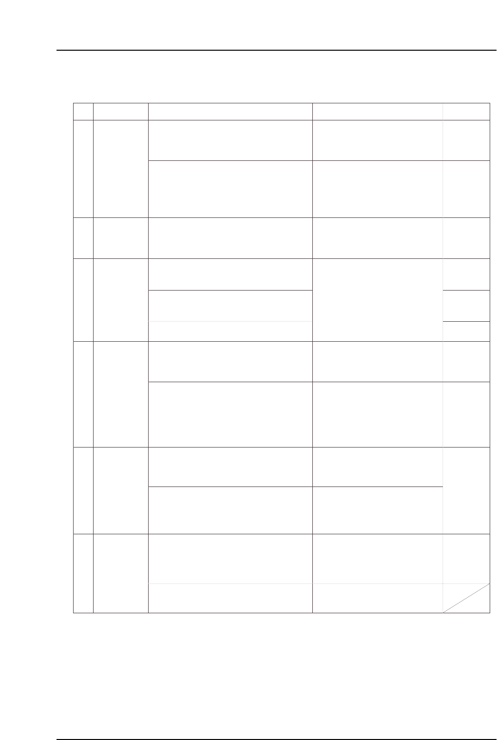
Part 5 Chapter 1 Troubleshooting Table
Edition 2.7 5-1-8 CP-7 series Mechanical Reference
No.
4-10
4-11
4-12
4-13
M: Part 1
Chapt 3
M: Part 1
Chapt 3
M: Part 1
Chapt 3
S: Part 3
Chapt 1
S: Part 3
Chapt 1
M: Part 1
Chapt 3
M: Part 1
Chapt 3
M: Part 1
Chapt 3
M: Part 2
Chapt 1
S: Part 3
Chapt 1
4-14
4-15
Lifter may not be moving all the way to
its motion limit position.
In-lifter UP/DOWN limit sensor fails to
switch on and off.
(1) Check the following sensors for problems
(3) - (6) (see above).
(2) Check the in-lifter UP/DOWN cylinder for
problem (7) (see above).
In-lifter cycle
error
Execute the following commands to see if the
lifter can be moved to its motion limit position:
[Panel Loader]-[Loader Maintenance]-[In-side]-
[Lifter Up/Lifter Down]-[START].
In-lifter UP limit check X0B5
In-lifter DOWN limit check X0B6
In-lifter panel
conveyance
error
(1) Check the following sensors for problems
(1) - (6) (described above).
(1) Check the following sensor for problems
(1) - (6) (described above).
Panel loading from the in-lifter to the in-
carrier began, but the panel arrival
sensor switched off before the in-carrier
was advanced.
A panel which should have been
unloaded has not been conveyed to
the X0CB sensor position. Look for a
failed ensor, a stuck panel, or a
missing panel.
Out-lifter UP/DOWN limit sensors fail
to switch off and on.
Lifter may not be moving all the way to
its motion limit position.
Out-conveyor panel arrival sensor fails
to switch on even though the panel has
been loaded from the out-carrier to the
out-lifter.
The panel spacing sensor between out-
conveyors 1 & 2 is off (it should be on).
Either the spacing sensor has failed, or
the sensor detection position is
improper.
Adjustable-rail engagement sensor
fails to switch on. Verify that the
conveyor width and the XY-table panel
conveyence width are properly aligned.
In-conveyor 1 panel arrival check X0AC
In-conveyor 2 panel arrival check X0AE
(1) Check the following sensors for problems
(3) - (6) (see above).
Out-conveyor 1 panel arrival check X0C7
Out-conveyor 2 panel arrival check X0C9
(2) Check the following sensor for problems
(1) - (6) (described above).
Out-conveyors 1 & 2 panel spacing check X0CA
Out-conveyor unloader panel arrival check X0CB
(1) Check the following sensors for problems
(3) - (6) (see above).
(2) Disconnect the machine's air supply and
return the adjustable rail to the correct
position.
(3) If the panel is caught at some point along the
conveyor, change the conveyor width.
Panel unloading
error
Out-lifter cycle
error
Cause Remedy Remarks Ref. Page
Out-lifter panel
conveyance
error
Adjustable-rail
engagement
error
(2) Check the out-lifter UP/DOWN cylinder for
problem (7)
(see above).
Execute the following commands to see if the
lifter can be moved to its motion limit position:
[PanelLoader]-[Loader Maintenance]-[Out-side]-
[Carrier Extend/Carrier Retract]-[START].
* The "X???" and "Y???" values which appear in the remedy column correspond to
the I/O map assignment numbers.
(2) Check the out-conveyor motor for problem
(7) (see above).
Out-conveyor motor ON Y02D
(1) Check the following sensors for problems
(3) - (6) (see above).
Out-lifter UP limit check X0D0
Out-lifter DOWN limit check X0D1
Adustable-rail engagement check (IN) X0C0
Adjustable-rail engagement check (OUT) X0DB
Adjustable rail engagement check (CENTER) X0DC

Part 5 Chapter 1 Troubleshooting Table
Edition 2.7 5-1-9 CP-7 series Mechanical Reference
No.
4-16
4-17
M: Part 1
Chapt 3
M: Part 1
Chapt 3
S: Part 3
Chapt 1
XY-table clamp
error
(1) Verify that the XY-table is clamping panels
properly.
(2) Check the following sensors for problems
(3) - (6) (see above).
• Panel was clamped, but the clamp
sensor failed to switch on, and the
unclamp sensor failed to switch off.
• Panel was unclamped, but the
unclamp sensor failed to switch on,
and the clamp sensor failed to switch
off.
The clamping cylinder may not be
moving all the way to its motion limit
position.
Reference pin insertion sensor fails to
switch on.
XY-table reference pin insertion check X059
XY-table raised clamper check X05A
XY-table panel clamp check (fixed-rail side, right) X05F
XY-table panel clamp check (adjustable-rail, right) X060
XY-table panel unclamp check (fixed-rail, righ X061
XY-table panel unclamp check (adjustable-rail, right) X062
XY-table panel clamp check (fixed-rail, left) X063
XY-table panel unclamp check (fixed-rail, left) X064
(1) Check the following sensors for problems
(3) - (6) (see above).
XY-table
unclamp error
Cause Remedy Remarks Ref. Page
(3) Check the panel clamping/unclamping
cylinder for problem (7) (see above).
Execute the following commands to see if the
cylinder can be moved to its motion limit position:
[Panel Loader]-[Clamp/Unclamp]-[START].
* The "X???" and "Y???" values which appear in the remedy column correspond to
the I/O map assignment numbers.
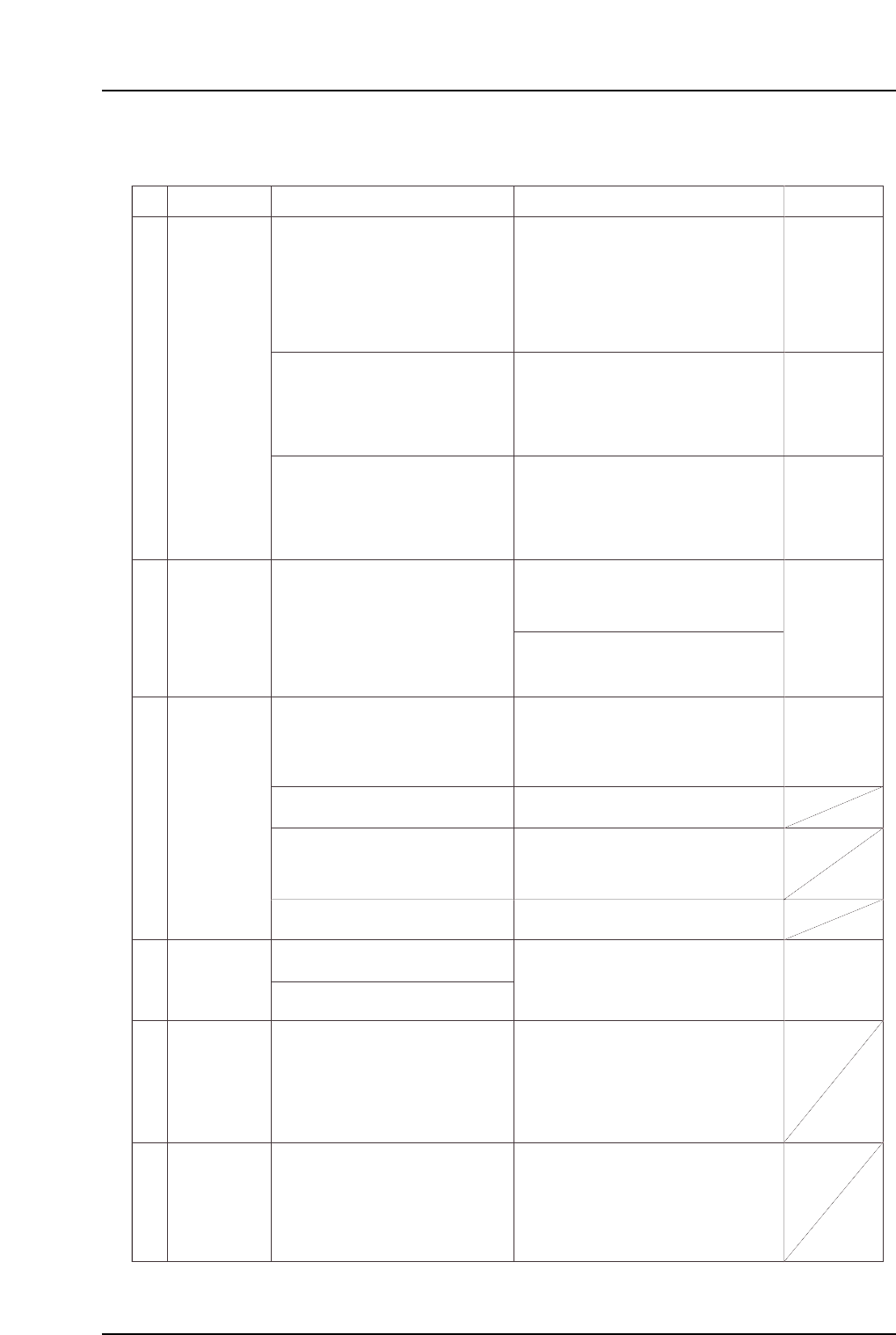
1.5 Missing Parts
No.
M: Part 3
Chapt 1
M: Part 3
Chapt 3 "3.1"
M: Part 2
Chapt 2
M: Part 4
Chapt 1 "1.11"
5-1
5-2
5-3
5-4
5-5
5-6
T: Part 3,
Lesson 2
"2.1.3"
U: Part 2
Chapt 4
"Nozzle"
"Speed"
T: Part 3
Lesson 2
"2.1.3"
U: Part 2
Chapt 4
"Speed"
T: Part 3
Lesson 2
"2.1.1"
U: Part 2
Chapt 4
"Appearance"
Incorrect Part
data setting.
Specify the appropriate nozzle size and
cam speed settings using the Tech
Report issued by Fuji as a reference.
If accuracy deviations or missing parts
are occurring for a specific part,
decrease the XY table speed setting in
the Part data where the problem is
occurring.
Unsuitable nozzle size, part weight, and cam
speed, etc., settings can result in an
insufficient holding force when handling
parts, causing nozzle and part slippage.
The Fuji Tech Report is meant for reference
purposes only.
The recommended cam speed may be
different even if the part shape is the same.
An unsuitable XY table speed can apply a
force which exceeds the holding capacity of
the part's solder, resulting in position
deviations. Solder adhesion decreases
when it dries. Therefore, the sooner
placement occurs after printing, the better.
Errors in the part height information or in the
table reference height Proper data
information can cause missing parts.
Fuji recommends that the actual part be
measured, with the measured value being
entered as the part height setting in Part data.
A stuck nozzle will prevent the parts from
being pushed in far enough when being
mounted, and may result in the parts being
returned.
Parts may be returned if solder, etc., is
adhering to the nozzle tip.
A misalignment between the ST9 nozzle
DOWN limit and the board height can
prevent parts from being pushed in far
enough when being placed, and may affect
placing accuracy.
Note: If a problem is found, contact your Fuji
agent.
Note: Machine adjustments can be performed
only by those with a Level 3 training.
Vacuum break problems can result in parts
being returned.
The solder printing condition or dryness can
cause part deviations during board
conveyance, or can affect the self-alignment
at reflow operations.
Solder adhesion weakens when the solder
dries. Therefore, the sooner placement
occurs after printing, the better.
Improper reflow conditions can cause self-
alignments and tombstoning.
Provide a profile in which the temperature is
increased evenly over the entire board. If the
solder's melting speed differs from point to
point, parts will be pulled toward the solder
that melts first.
Improper ST9 cylinder operation may
prevent parts from being placed correctly.
Note: If a problem is found, contact your Fuji
agent.
(1) Press the reflective disk to verify
that the nozzle spring-back motion
is smooth.
(2) Check to see if the nozzle is clogged.
(3) Check to see if foreign matter has
adhered to the nozzle tip.
Replace the nozzle if any of the above
problems are found.
Defective
nozzle.
Placement
height problem.
Vacuum break
problem
Printing
conditions
problem.
Reflow
conditions
problems.
Cause Remedy Remarks Ref. Page
Check for errors in the part height
information.
Check the backup pin height, quantity,
and configuration, and check the board's
flatness.
Check to see if the XY-table is level.
Replace the cylinder unit if abnormal
noise is emitted from the cam box
uring automatic operation, or if the
nozzle DOWN limit position is incorrect.
Check for a problem with the Proper
data Z0 (0.3mm push in).
Replace mechanical valves where the
spool motion is not smooth.
Adjust the vacuum break lever position
and the speed controller.
Check the solder condition after printing.
Check the reflow temperature profile.
Part 5 Chapter 1 Troubleshooting Table
Edition 2.7 5-1-10 CP-7 series Mechanical Reference