CP-7[732-742]-series Mechanical Reference(2.9E).pdf - 第162页
Part 4 Chapter 1 Station Adjustments Edition 2.4 4-1-12 CP-7 series Mechanical Reference 1.4.3 Adjusting the Nozzle UP Limit Sensor The sensor which detects the height of the nozzle UP/DOWN rod is mounted inside the cam …
Part 4 Chapter 1 Station Adjustments
Edition 2.4 4-1-11 CP-7 series Mechanical Reference
1.4.2 Confirming the Pick-up Height
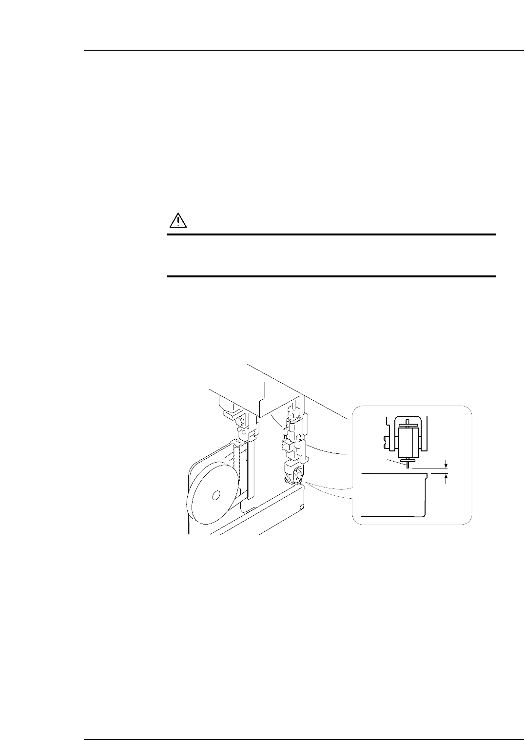
Ensure that the nozzle descends low enough to pick up a part set in the feeder. Confirm
that the mechanical valve movement creates a vacuum for part pick-up.
1. Set a W8xP4 mm feeder (with tape leaf removed) at the D1 position.
2. Move the feeder to station 1 by pressing [Position] - (Position) [D1-axis] - enter [1]
- [OK] - START.
3. Check that the NZ-axis is stopping at the position specified at the "PICK UP POS.
NZ" item in Proper data.
WARNING
Exercise extreme caution when working on the machine if
the cam is not at its origin (0 deg.). Recoil of the cam axis
can endanger the operator.
4. Set the cam angle to 0 degrees, then turn the first nozzle solenoid valve on to work
the cam lever.
5. Use the inching keys to rotate the cam to 170°.
6. Use a thickness gauge to ensure a space of 0.65 mm between the tip of the nozzle
and the feeder (pick-up height).
0.65 mm
Feeder
Nozzle
C7SM4014
Part 4 Chapter 1 Station Adjustments
Edition 2.4 4-1-12 CP-7 series Mechanical Reference
1.4.3 Adjusting the Nozzle UP Limit Sensor
The sensor which detects the height of the nozzle UP/DOWN rod is mounted inside the
cam box. Adjust the sensor’s mounting position so that the sensor switches ON when
the nozzle is at its UP limit.
1. Press the EMERGENCY STOP button to take the 200V down to 100V.
WARNING
• Always be sure to cut off the 200V power before carrying
out any work.
• Exercise extreme caution when working on the machine if
the cam is not at its origin (0 deg.). Recoil of the cam
axis can endanger the operator.
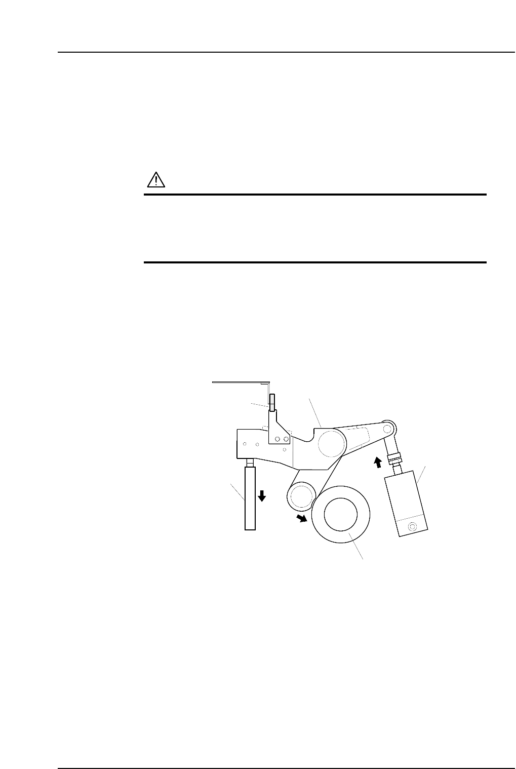
2. Set the cam axis at the 0-degree position.
3. Activate the ST1 pick-up solenoid air cylinder (located in the cam box):
Execute the I/O commands: [Maintenance] - [I/O Check] - [Standard I/O] - [Y031
ST1 PICKUP SOL ENGAGED] - [Output Signal ON]
The cam lever will then follow the cam axis.
1ST Pick-up solenoid
air cylinder
Cam lever
Nozzle up limit sensor
Nozzle UP/DOWN
rod
Cam axis
Cam lever follows the cam axis.
C7SM4015a
Part 4 Chapter 1 Station Adjustments
Edition 2.4 4-1-13 CP-7 series Mechanical Reference
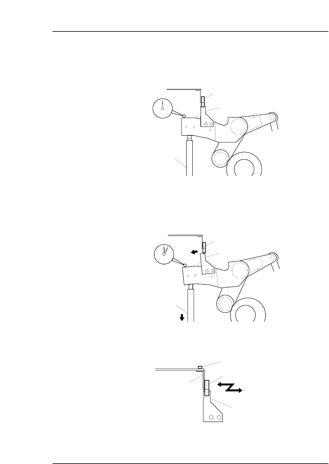
4. Place a dial gauge on the top end of the cam lever and set the gauge reading to
“0”. In this condition, the cam axis will be at its 0-degree position, and the nozzle
UP/DOWN rod will be at its UP limit position. Verify that the nozzle UP limit
sensor is ON (X030 ST1 CYLINDER UPPER-LIMIT is ON) at the I/O screen.
5. While observing the dial gauge, rotate the cam axis in the forward direction to
lower the nozzle UP/DOWN rod. Adjust the sensor’s mounting position so that
the sensor switches OFF (X030 ST1 CYLINDER UPPER-LIMIT switches OFF)
when the rod has been lowered 0.3 to 0.4 mm.
6. Adjust the sensor’s mounting position by loosening the sensor lock screw and
sliding the sensor in the front/back directions.
C7SM4018a
Nozzle up limit sensor
Screw
Sensor bracket
Dog
Dog
Nozzle UP/DOWN
rod
Nozzle up limit sensor (OFF)
C7SM4017
C7SM4016
Dog
Nozzle UP/DOWN
rod
Set the dial gauge
to "0"
Nozzle up limit sensor (ON)