CP-7[732-742]-series Mechanical Reference(2.9E).pdf - 第180页
1.10.2 Adjusting the Nozzle UP Limit Sensors The nozzle UP limit sensor which detects the up limit position of the nozzle UP/DOWN rod at station 9 is mounted inside the cam box. Adjust the mounting position of this senso…
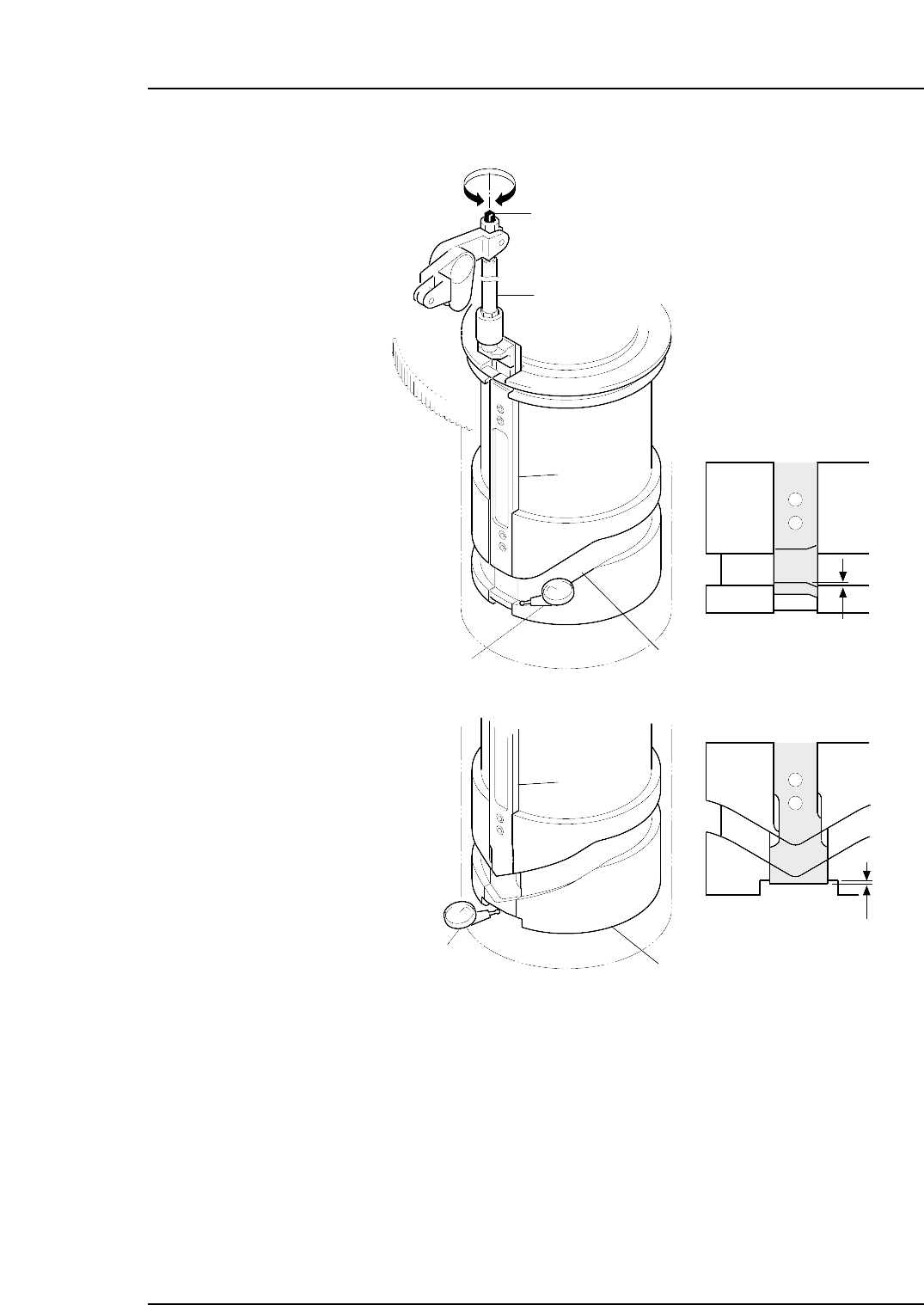
6. Adjust the rod.
• CP-732E
Adjust the rod so that there is ±0.02 mm difference between the slider groove
and the cam groove.
• CP-742ME/CP-742E
Adjust the length of the rod using the bolt to ensure that the distance between
the base of the slider and the cut out section in the cylindrical cam is within the
range of ±0.02 mm.
7. Reattach the placing head assembly in the original location.
Using the clutch alignment jig, reverse the removal procedures to attach the
assembly.
Slider
Cam groove
Slider
Cylindrical cam
Rod
Adjustment bolt
–0.02 mm
–0.02 mm
C7SM4028a
Dial gauge
Dial gauge
<CP-732E>
<CP-742ME/
CP-742E>
Part 4 Chapter 1 Station Adjustments
Edition 2.4 4-1-29 CP-7 series Mechanical Reference
1.10.2 Adjusting the Nozzle UP Limit Sensors
The nozzle UP limit sensor which detects the up limit position of the nozzle UP/DOWN
rod at station 9 is mounted inside the cam box. Adjust the mounting position of this
sensor so that it switches ON when the nozzle is at its UP limit position.
1. Press the EMERGENCY STOP button to take the 200V down to 100V.
WARNING
• Always be sure to cut off the 200V power before carrying
out any work.
• Exercise extreme caution when working on the machine if
the cam is not at its origin (0 deg.). Recoil of the cam
axis can endanger the operator.
2. Set the cam axis at the 0-degree position.
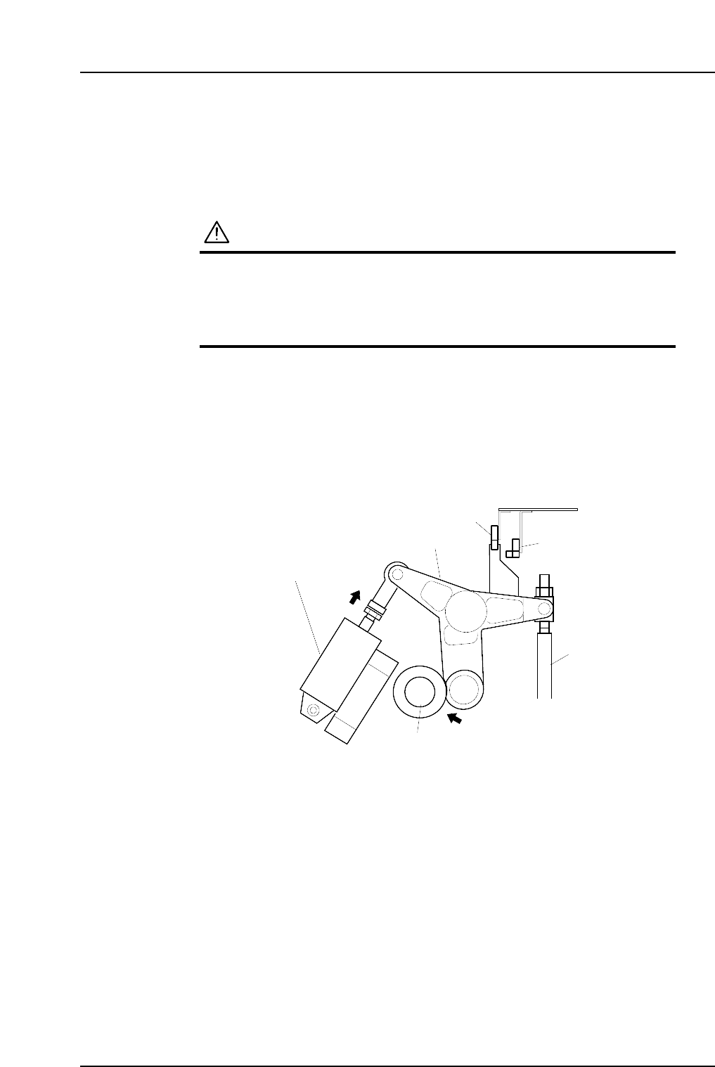
3. Activate the ST9 placing solenoid air cylinder (located in the cam box):
Execute the following I/O commands: [Maintenance] - [I/O Check] - [Standard I/O]
- [Y035 ST9 PLACE SOL ENGAGED] - [Output Signal ON]
The cam lever will then follow the cam axis.
9ST Place solenoid
air cylinder
Cam lever
Nozzle UP/DOWN rod
Cam axis
Cam lever follows
the cam axis.
C7SM4029a
Nozzle up limit sensor
Nozzle down limit sensor
Part 4 Chapter 1 Station Adjustments
Edition 2.4 4-1-30 CP-7 series Mechanical Reference
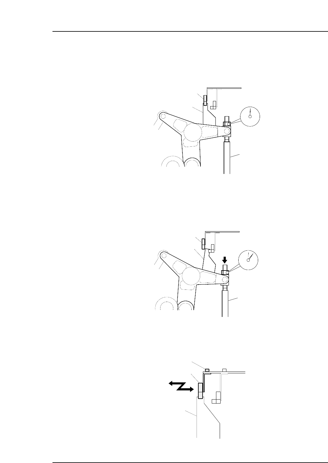
4. Place a dial gauge on the top end of the cam lever and set the gauge reading to
“0”. In this condition, the cam axis will be at its 0-degree position, and the nozzle
UP/DOWN rod will be at its UP limit position. Verify that the nozzle UP limit
sensor is ON (X032 ST9 CYLINDER UPPER LIMIT is ON).
5. While observing the dial gauge, rotate the cam axis in the forward direction to
lower the nozzle UP/DOWN rod. Adjust the sensor’s mounting position so that
the sensor switches OFF (X032 ST9 CYLINDER UPPER-LIMIT switches OFF)
when the rod has been lowered 0.3 to 0.4 mm.
6. Adjust the sensor’s mounting position by loosening the sensor lock screw and
sliding the sensor in the front/back directions.
C7SM4032
Nozzle up limit sensor
Screw
Dog
C7SM4031
Nozzle up limit sensor (OFF)
Dog
Nozzle Up/Down rod
Rod lowered 0.3 to 0.4 mm
C7SM4030
Nozzle up limit sensor (ON)
Dog
Nozzle UP/DOWN rod
Set the dial gauge
to "0"
Part 4 Chapter 1 Station Adjustments
Edition 2.4 4-1-31 CP-7 series Mechanical Reference