CP-7[732-742]-series Mechanical Reference(2.9E).pdf - 第33页
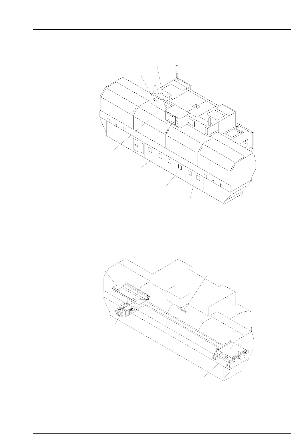
Part 1 Chapter 1 Machine Components Edition 2.4 1-1-6 CP-7 series Mechanical Reference Rear Side C7SM1011a Vacuum pump Waste tape cutter Pallet Device table C7SM1010a Operation box 2 Rear cover Servo box 3 (Servo BKT 2) …
<CP-742E>
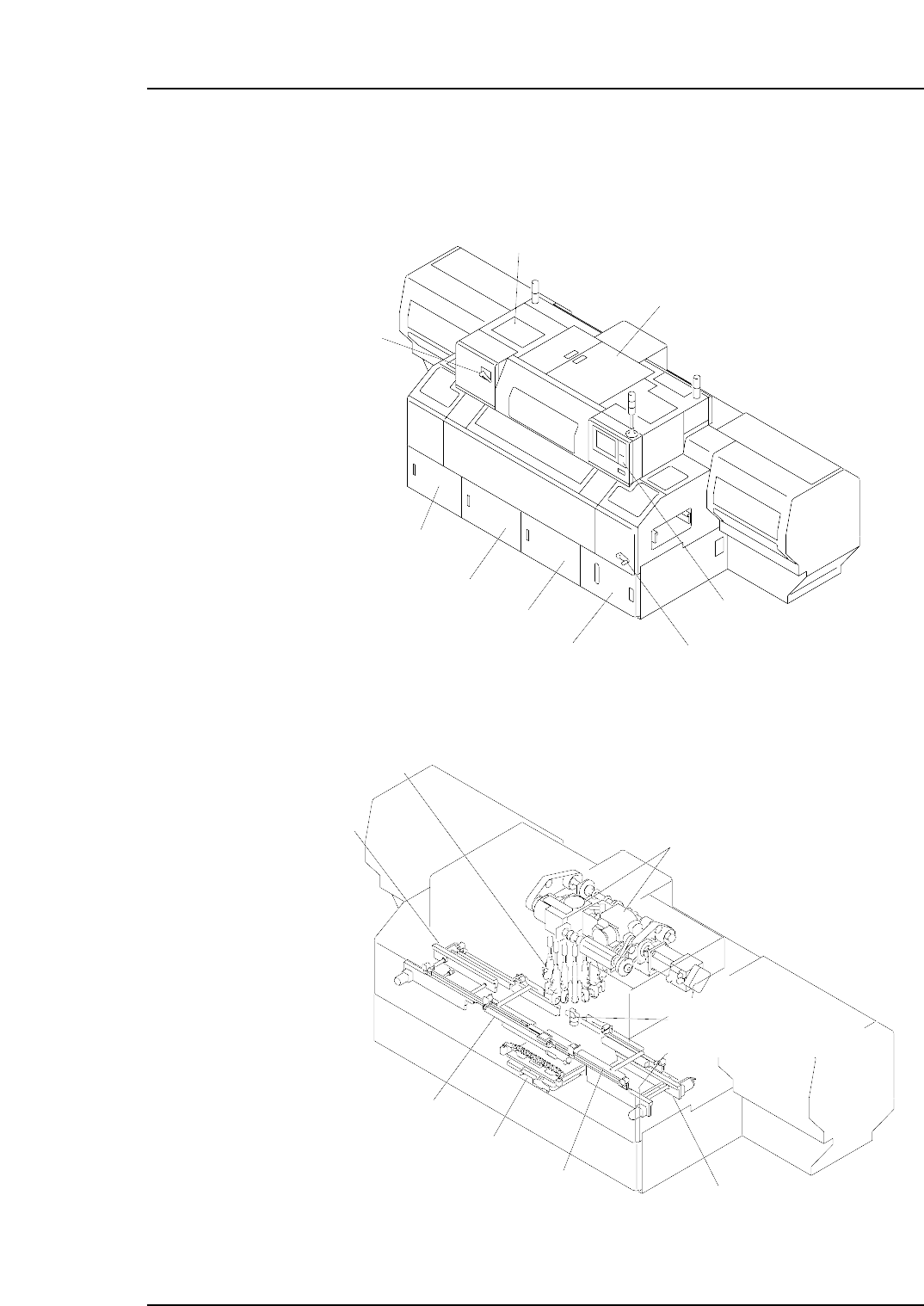
Front Side
C7SM1009a
In-conveyor
Placing head
Index unit
Out-conveyor
In-carrier
XY-table
Vision processing camera
(for reading fiducial mark)
Out-carrier
C7SM1008b
Breaker
Oil cooler box
Cam box
Operation box 1
Conveyor width adjusting handle
Waste tape box
Control box 2
Control box 3
Control box 1
CP-742E
Part 1 Chapter 1 Machine Components
Edition 2.4 1-1-5 CP-7 series Mechanical Reference
Part 1 Chapter 1 Machine Components
Edition 2.4 1-1-6 CP-7 series Mechanical Reference
Rear Side
C7SM1011a
Vacuum pump
Waste tape cutter
Pallet
Device table
C7SM1010a
Operation box 2
Rear cover
Servo box 3
(Servo BKT 2)
Servo box 2
(Servo BKT 1)
Servo box 1
Transformer box
(Transformer BKT)
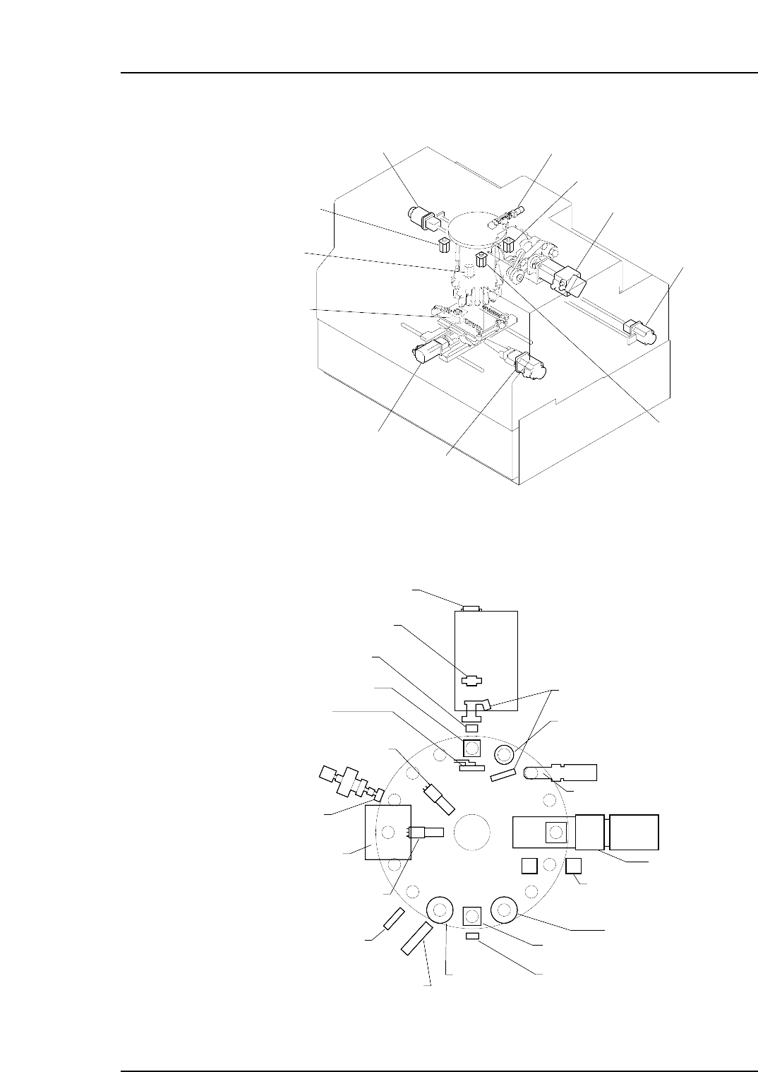
Servo Control Axes
Note: The above figure shows the CP-732E, but the position of the servo motors is the same on
the CP-742ME/742E.
Rotary Head
Station 1
Tape end detection
Station 2
Large parts check
Station 2
Pre-theta
Station 8
Fine theta
Station 9
Placing nozzle up/down
Station 10
Nozzle clutch origin position
Nozzle clutch engagement check
Station 10
Reverse theta
Station 11
Head A detection
Station 13
Reject dump parts
Station 14
Nozzle change
Station 13
Nozzle pre-change check
Station 15
Nozzle post-change check
Station 9
Mechanical valve switch
Station 3
Nozzle theta axis position
Station 5
Vision processing
Station 1
Feeder advance
Station 1
Mechanical valve switch
Station 1
Picking nozzle up/down
Waste tape cut
C7SM1017a
Station 6
Parts height check,
nozzle length check (Option)
C7SM1016a
X-axis motor
Y-axis motor
Z-axis motor
D1-axis motor
D2-axis motor
NC-axis motor
NZ-axis motor
Cam axis motor
FQ-axis motor
PQ-axis motor
RQ-axis motor
Part 1 Chapter 1 Machine Components
Edition 2.4 1-1-7 CP-7 series Mechanical Reference