CP-7[732-742]-series Mechanical Reference(2.9E).pdf - 第165页
Part 4 Chapter 1 Station Adjustments Edition 2.4 4-1-15 CP-7 series Mechanical Reference 1.5.2 V alve Switching Lever Height Adjustment This adjustment should be performed on the reference head after completing adjustmen…
Part 4 Chapter 1 Station Adjustments
Edition 2.4 4-1-14 CP-7 series Mechanical Reference
1.5 Mechanical Valve Switching (Station 1)
Point
The nozzle vacuum goes from OFF to ON with the movement of the mechanical valve at
station 1. Vacuum pressure for part pick-up forms inside the nozzle when the valve is
open.
1.5.1 Checking the Position of the Pin Bracket
1. Press the EMERGENCY STOP button to turn off the 200V power, leaving only the
100V power on.
WARNING
Always be sure to cut off the 200V power before carrying
out any work.
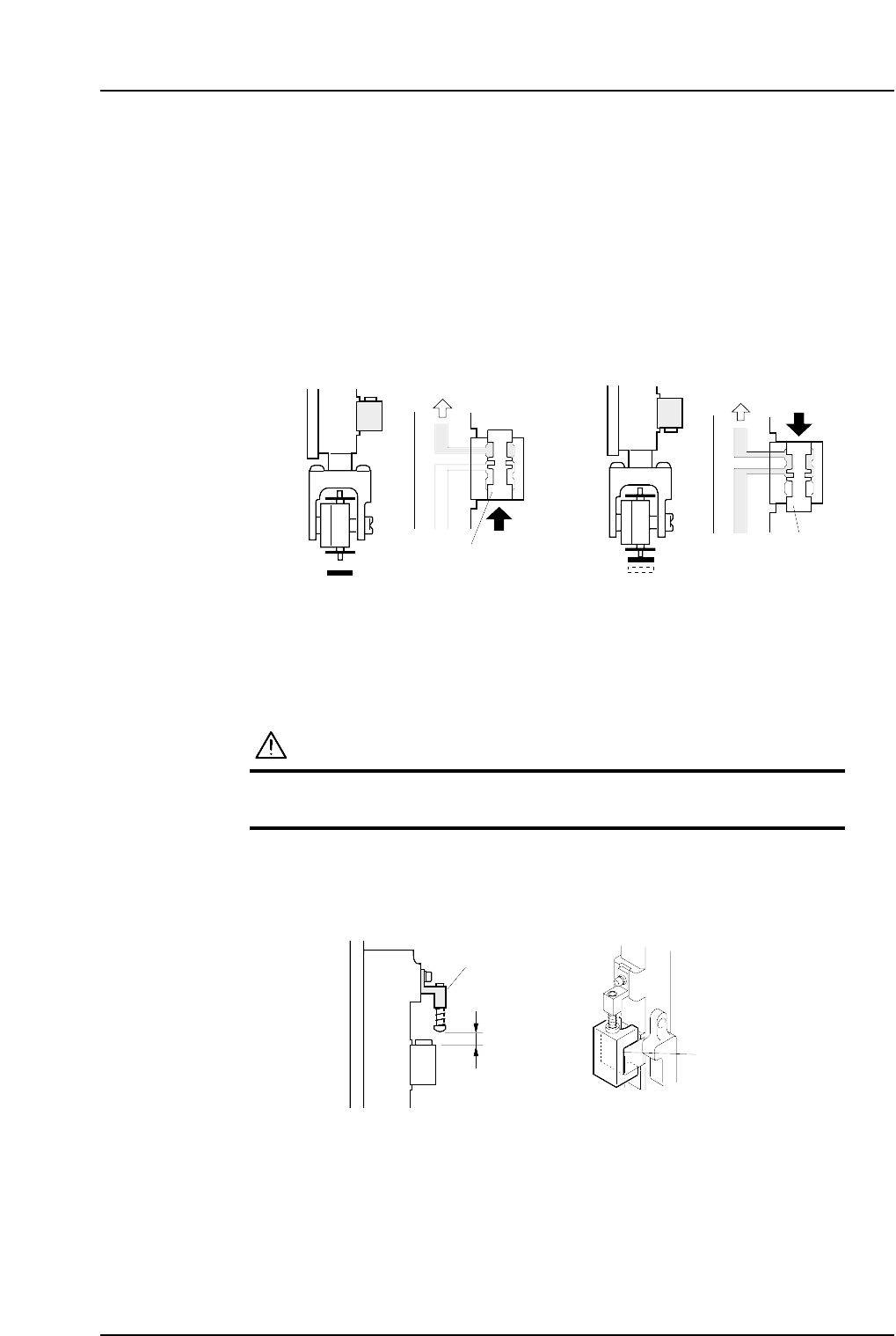
2. Ensure that distance A (as seen in the figure below) is 8.9 mm for all heads. Use a
special jig (Z9526DCPJ0371) to check this distance.
8.9 mm
Pin bracket
Jig
( Z9526DCPJ0371 )
C7SM4054a
A
Vaccum ONVaccum OFF
Vaccum
Vaccum
Spool
Spool
< Spool pushed up > < Spool pushed down >
C7SM4019a
Part 4 Chapter 1 Station Adjustments
Edition 2.4 4-1-15 CP-7 series Mechanical Reference
1.5.2 Valve Switching Lever Height Adjustment
This adjustment should be performed on the reference head after completing
adjustments to the vertical movement of the nozzle. (Refer to 1.4 “Nozzle Vertical
Movement During Pickup” for details.)
The reference head can be identified by its height. All heads are measured with spools
lifted, and the lowest one is referred to as the reference head.
1. Press the EMERGENCY STOP button to take the 200V down to 100V.
WARNING
• Always be sure to cut off the 200V power before carrying
out any work.
• Exercise extreme caution when working on the machine if
the cam is not at its origin (0 deg.). Recoil of the cam
axis can endanger the operator.
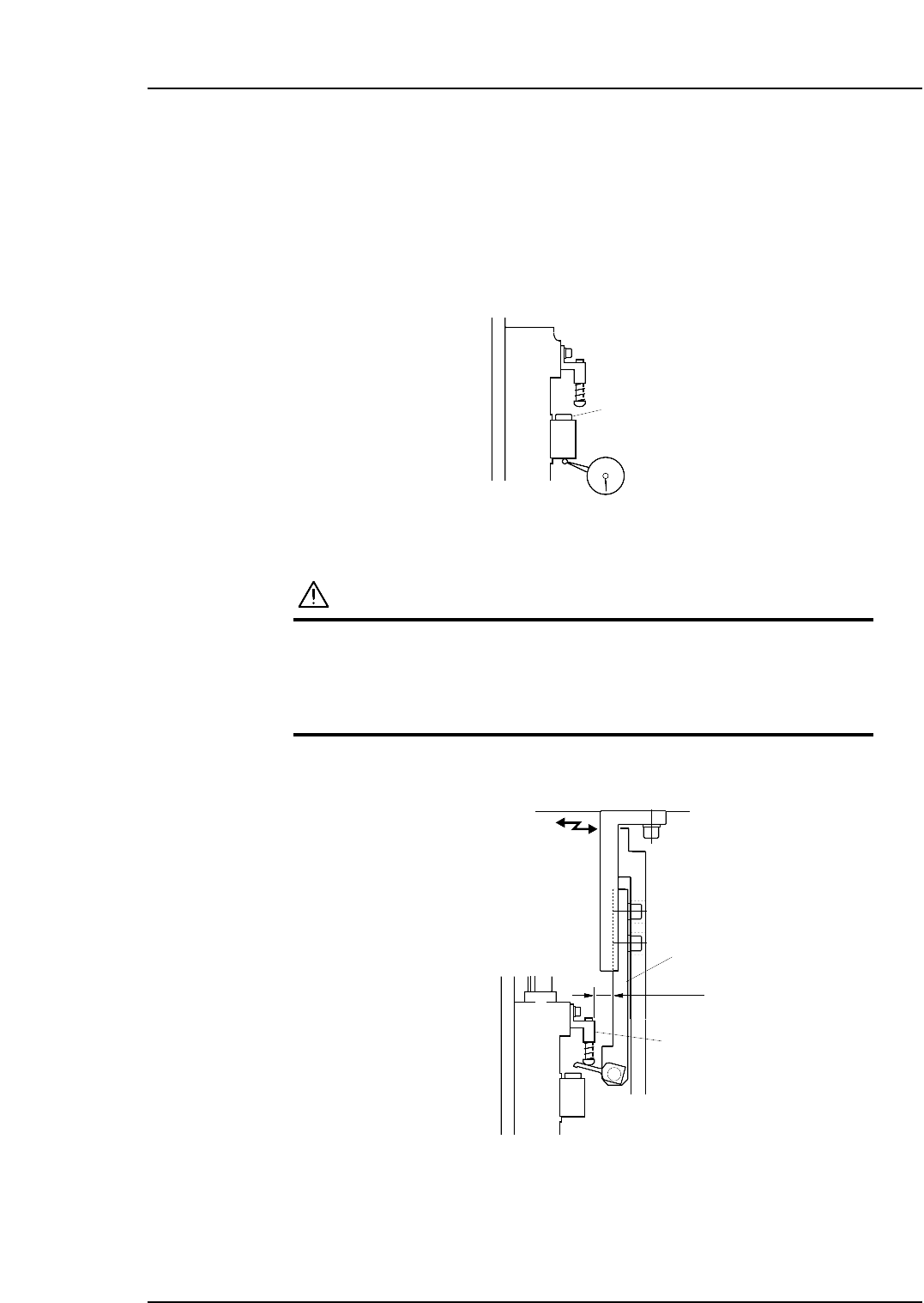
2. Adjust the position of the lever bracket so that the distance from the pin bracket is
12 mm.
3. With the Y030 ST1 PICKUP SOL DISENGAGED ON, use the cam handle to rotate
the cam to 170°.
Lever bracket
Pin bracket
C7SM4056
12 mm
Spool
C7SM4055
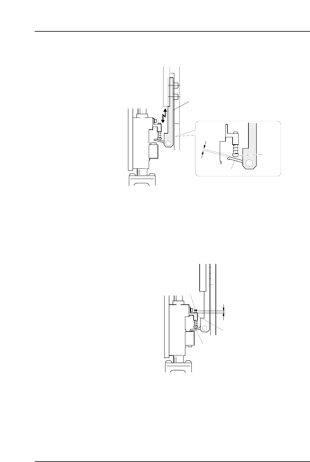
4. Adjust the height of the bracket so that the distance between the lever and the pin
is 0.6 mm.
5. Return the cam angle to 0 degrees. Switch on the 1st nozzle UP/DOWN solenoid
valve in order to work the cam lever.
Check the servo counter to verify that the Proper data (PICK UP POS. NZ) is at the
pick-up height (approx. 4000 pulse position).
6. Use the cam handle to rotate the cam to 170 degrees.
7. Ensure that the clearance of the pin from the bracket is within the range of 0.5 to
1.0 mm after the pin has been raised by the lever.
0.5~1.0 mm
Pin bracket
Pin
Lever
C7SM4021a
Lever bracket
C7SM4020a
0.6 mm
Lever
Pin
Part 4 Chapter 1 Station Adjustments
Edition 2.4 4-1-16 CP-7 series Mechanical Reference