CP-7[732-742]-series Mechanical Reference(2.9E).pdf - 第80页
1.5 Cleaning the Camera Glass (W eekly) Point The camera glass should be cleaned once a week to ensure that a clear image is being acquired. This also contributes to stable vision processing and part pick-up operations. …
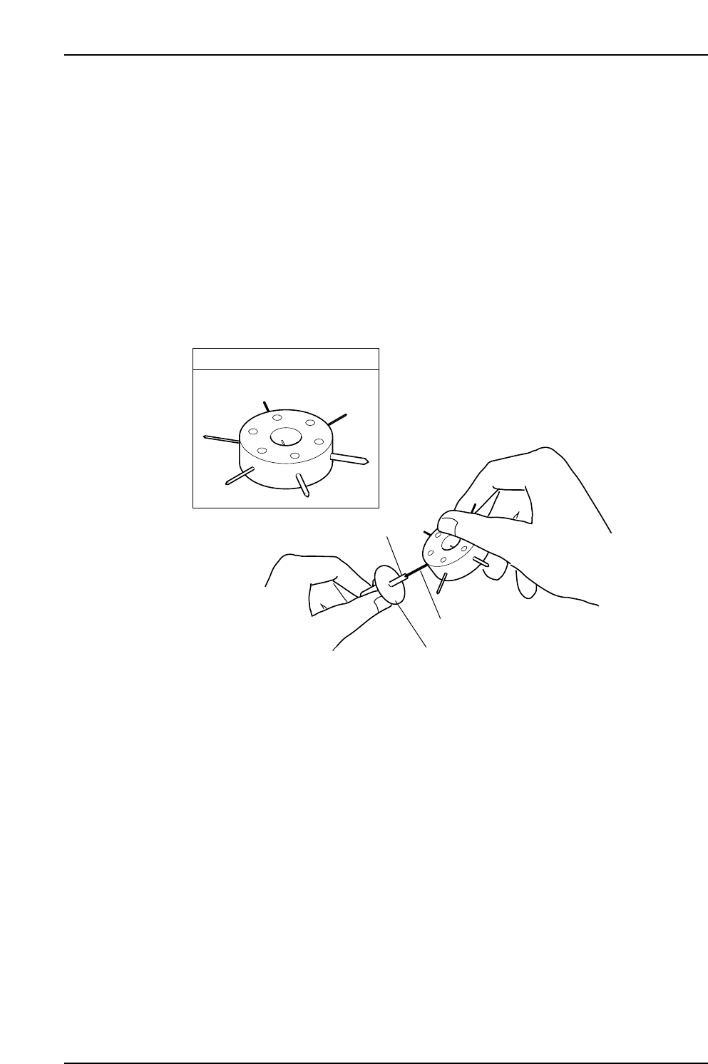
1.4 Cleaning the Nozzle Interior (Weekly)
Point
Because the part is held by vacuum through the nozzle, minute dust or glue particles,
etc., can build up inside the nozzle tube, causing clogging. Such clogging can reduce the
nozzle suction and cause problems when picking up parts. The nozzle tube should be
cleaned out weekly, or when clogging occurs.
Procedure
Use an appropriately sized drill bit to remove foreign matter from inside the nozzle tube.
When cleaning is complete, check the drill bit to ensure that dirt from the nozzle has not
adhered to the tip.
Note: Jig AWPJ8100 cannot be used for ø0.4 nozzles.
Caution:
1. Take care to avoid bending the nozzle.
2. Take care to avoid dirtying the surface of the fluorescent sticker.
C7SM3005a
Nozzle
Drill bit
Fluorescent nozzle sticker
JIG No. AWPJ8100
Part 3 Chapter 1 Cleaning
Edition 2.9 3-1-4 CP-7 series Mechanical Reference
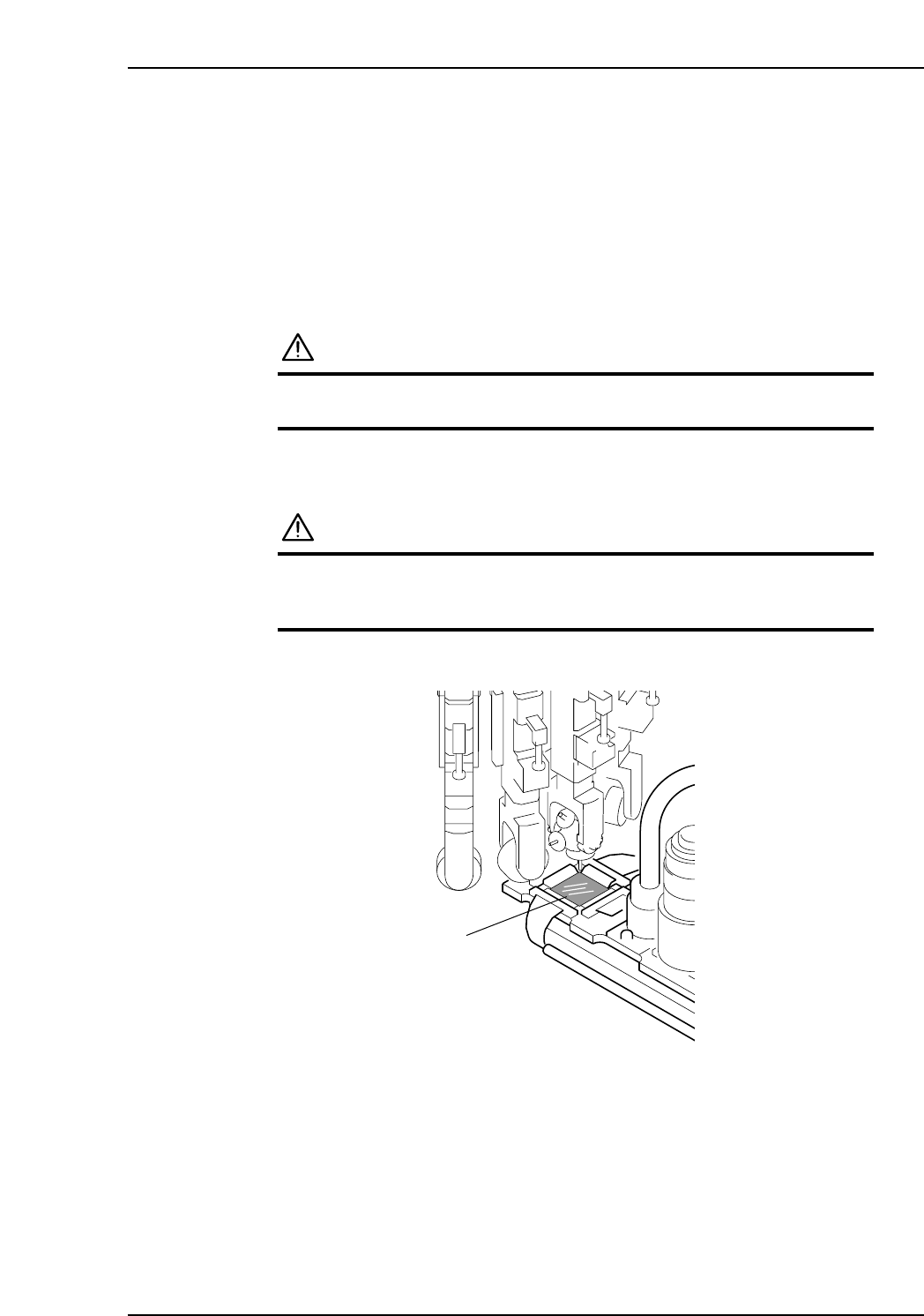
1.5 Cleaning the Camera Glass (Weekly)
Point
The camera glass should be cleaned once a week to ensure that a clear image is being
acquired. This also contributes to stable vision processing and part pick-up operations.
Procedure
WARNING
Be sure to turn the main power off before performing this
procedure.
Use a soft brush (such as those used to clean camera lenses) to clean the camera glass. If
the glass is badly soiled, use a commercially available glass cleaner.
CAUTION
Take care to not bend any nozzles.
Do not place excessive pressure on the camera cover
glass, which is thin and breaks easily.
C7SM3010a
Camera glass
Part 3 Chapter 1 Cleaning
Edition 2.9 3-1-5 CP-7 series Mechanical Reference
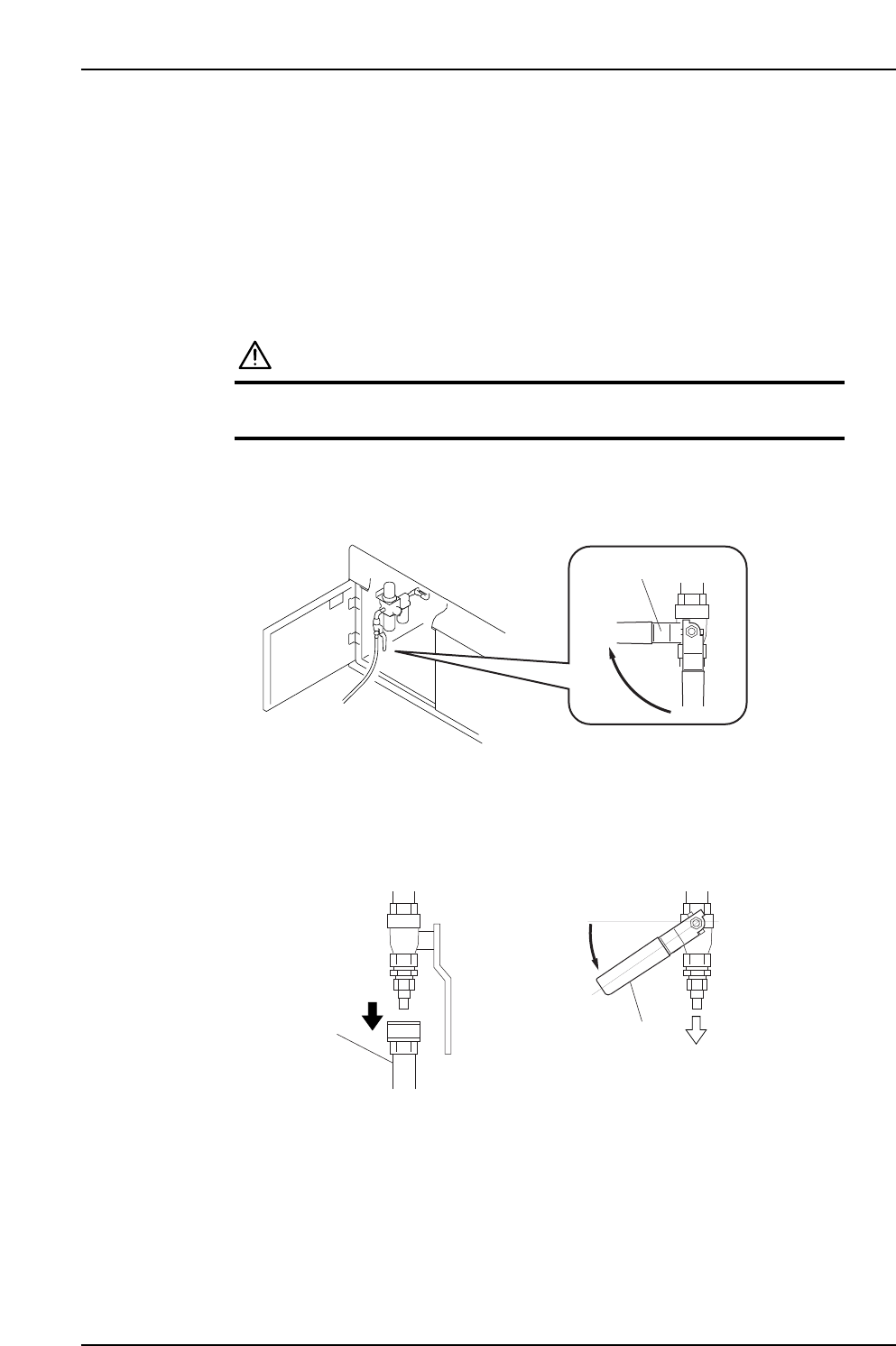
1.6 Cleaning the Filter Regulator (Weekly)
Point
The air that flows through the system’s air lines must always be clean. A soiled filter
regulator makes it impossible to supply clean air, and can cause equipment failure.
Procedure
CAUTION
Be sure to turn the air supply off before performing this
procedure.
Be sure to turn the air supply off and to release the air pressure in advance.
1. Close the air inlet valve lever and cut the external air-supply.
2. Reduce the pressure in the air hose.
After disconnecting the air hose, return the valve lever slowly to the position
indicated in the illustration below to expel the air from the air inlet.
3. Close the valve lever again when the air has been fully expelled.
Valve lever
Air
Air hose
Valve lever
Close
Part 3 Chapter 1 Cleaning
Edition 2.9 3-1-6 CP-7 series Mechanical Reference