00196351-04_UM_ACT_de_en.pdf - 第106页
ACT - Accurac y Check T ool / User Manual 07/2014 Edit ion 32 The next screen d ispla ys an exam ple of a rec ipe: NOTICE The dif ferent ACT glass c om ponent types ar e disp layed in differ ent col ors. For a succes sfu…
ACT - Accuracy Check Tool / User Manual 07/2014 Edition
31
► Drag the selected table to the required location.
► Use the empty tables to create a setup for ceramic pads, for instance.
NOTICE
If you create a setup with more than one table with ceramic pads, make sure that the
same component is not set-up at more than one location at the same time.
Predefined tables already exist for setting up the tray with the glass components.
NOTICE
● The X- and Y-offsets for the waffle pack trays on the tables have already been
entered! They may need to be corrected!
● The predefined Arbitrary Carrier tray holder should be left on track 21 and the ACT
X-table (Tray)holder should also be physically placed there. Otherwise, it is not
possible to pick-up with all segments (TH) on all machines.
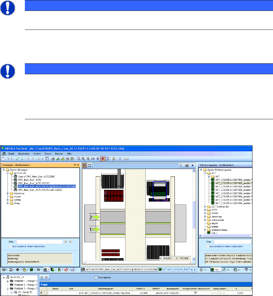
Figure 4-1 displays an example of a setup:
Figure 4-1: Setup on a D3 with Twin Head at gantry 3. Waffle pack tray with 16x4 glass components (CC02-05) on an
S-table
ACT - Accuracy Check Tool / User Manual 07/2014 Edition
32
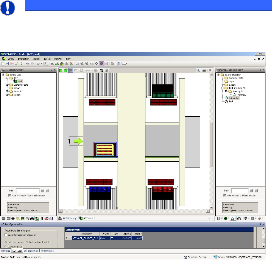
The next screen displays an example of a recipe:
NOTICE
The different ACT glass component types are displayed in different colors. For a
successful download to the station, the colors of the components in the tray and on the
board have to match each other. This is visible in the recipe.
Figure 4-2: Example of a recipe with ACT board and glass components (CC02-05)
► Make sure that the number of required nozzles is available in the nozzle changer for the head
to be measured, i.e. in accordance with the number of segments of the head to be measured.
ACT - Accuracy Check Tool / User Manual 07/2014 Edition
33
4.1.2 Selecting the Board (Placement Program)
► Select a suiting placement program for your head configuration from the pre-configured boards
(with the aid of Table 4-1).
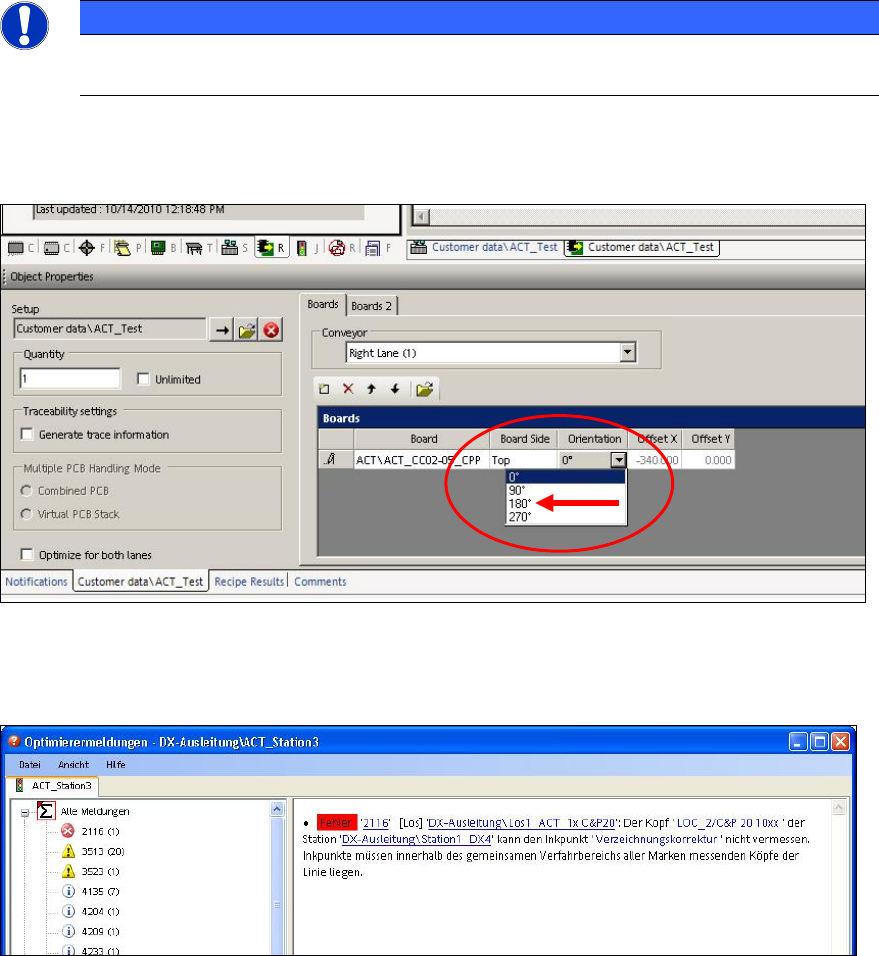
NOTICE
In order to access the fiducials, the ACT measuring plate has to be placed rotated by
180° in SIPLACE SX4 and DX4 machines.
Thus, if an ACT placement program is defined for a SIPLACE SX4 or DX4 machine, the orientation
(position) of the board has to be adapted to 180° in the created recipe.
Figure 4-3: Rotating board orientation by 180°on SX4, DX4
If this adaption of the board orientation is not performed, the following error message (example) is
already displayed on the SIPLACE Pro Line Control GUI during specification:
Figure 4-4: Example: Error message due to unavailable ink spots