00196351-04_UM_ACT_de_en.pdf - 第125页
ACT - Accurac y Check T ool / User Manual 07/2014 Edit ion 51 Figure 4- 30 : Dialog box: Enter PCB (example SIPLA CE D4) ► Now inser t the b oard int o the input s ection (see a lso se ction 4.2.2 ). The board g ets p la…
ACT - Accuracy Check Tool / User Manual 07/2014 Edition
50
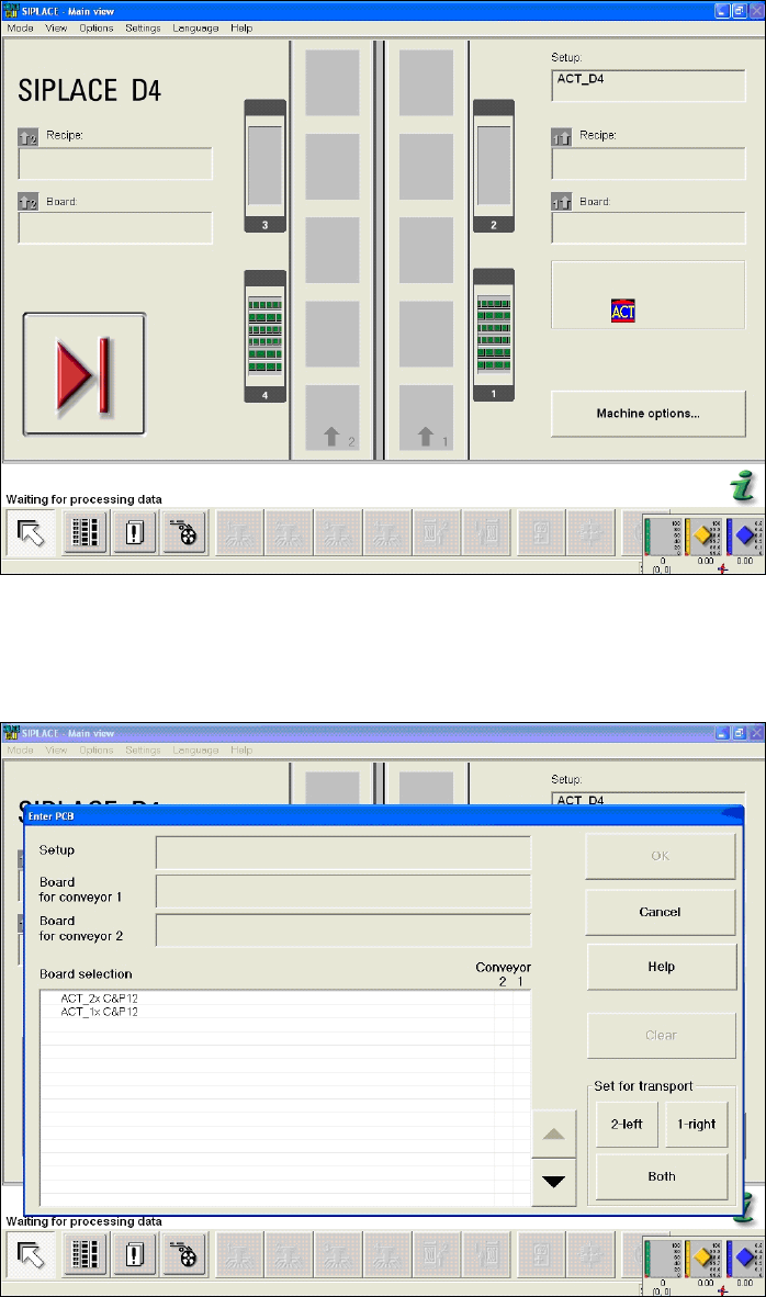
Figure 4-28: Dialog box after setting ACT mode. Display: ACT icon
The Enter PCB dialog box is opened (Figure 4-29).
► Select the ACT board.
Figure 4-29: Dialog box: Enter PCB (example SIPLACE D4)
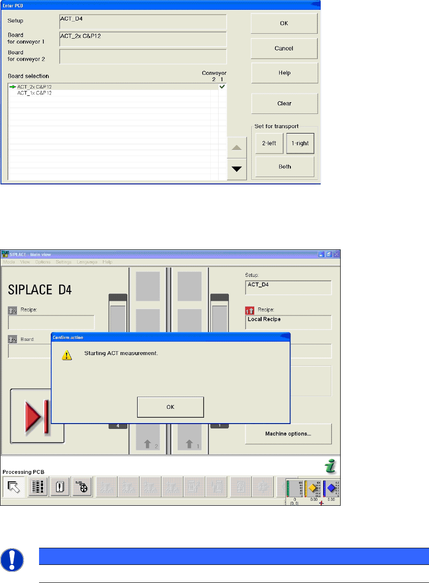
The Enter PCB dialog box is opened (Figure 4-30).
► Select the ACT board.
► Select the conveyor lane.
► Confirm your entry with OK.
ACT - Accuracy Check Tool / User Manual 07/2014 Edition
51
Figure 4-30: Dialog box: Enter PCB (example SIPLACE D4)
► Now insert the board into the input section (see also section 4.2.2).
The board gets placed and then the measurement starts automatically.
Figure 4-31: Message for ACT measurement (example SIPLACE D4)
NOTICE
The machine should not be operated during measurement!
A dialog box will open in which the current measurement operation is displayed. The fiducials that
are currently being measured are displayed.
ACT - Accuracy Check Tool / User Manual 07/2014 Edition
52
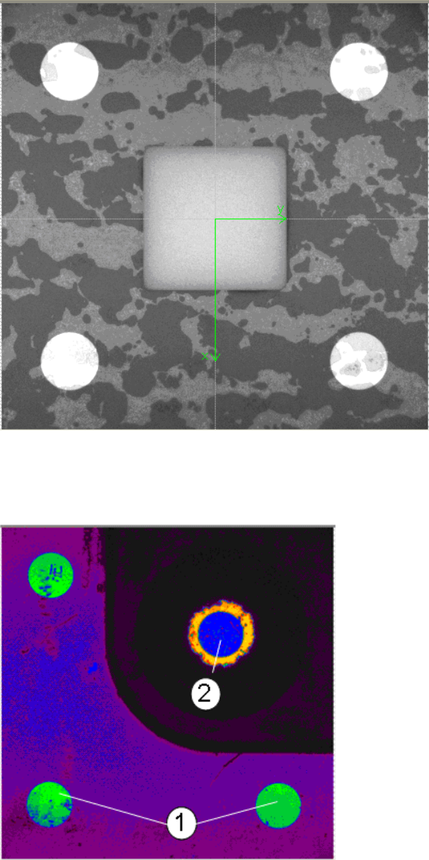
Example of measurement operation with the ceramic components Cerampads:
Figure 4-32: Example of measurement window with Cerampads
Example of measurement operation with glass components:
Figure 4-33: View of measurement window with glass components (pseudo color view)
Key:
(1) Fiducials on the ACT plate (2) Fiducials on the glass component