00196351-04_UM_ACT_de_en.pdf - 第116页
ACT - Accurac y Check T ool / User Manual 07/2014 Edit ion 42 4.2.2 Inserting the Pla te ► Insert the glass pl ate with the i ncident light pl ate (blac k m etal plate) und erneath it in t he input section. NOTICE The m …
ACT - Accuracy Check Tool / User Manual 07/2014 Edition
41
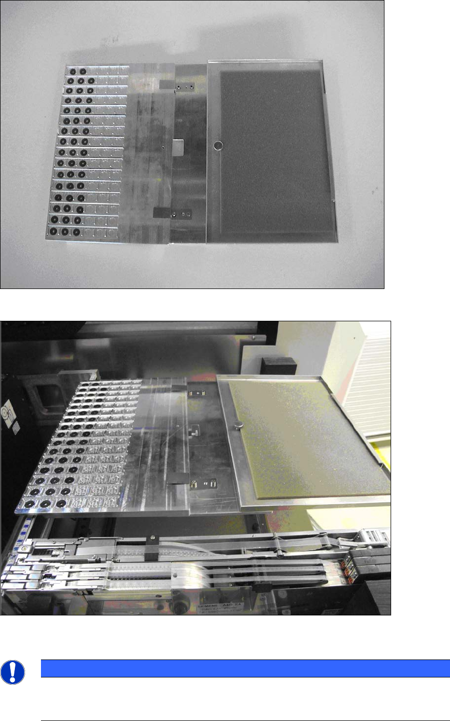
Figure 4-14: Intervention guard completely mounted
Figure 4-15: Tray set up with intervention guard
NOTICE
The gaps still remaining to the left and right of the tray must be closed off with the
dummy feeders described above so that full protection against intervention in the
machine from the outside is ensured.
ACT - Accuracy Check Tool / User Manual 07/2014 Edition
42
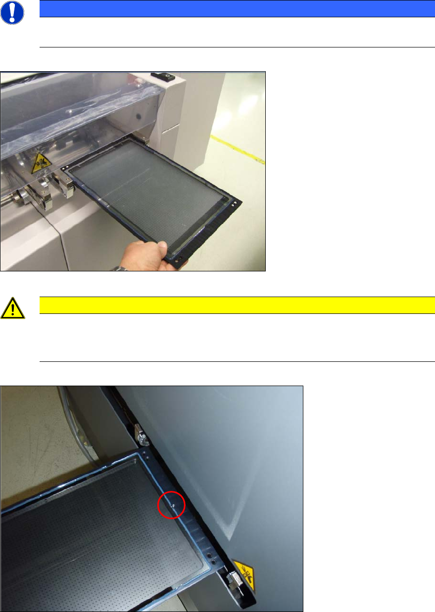
4.2.2 Inserting the Plate
► Insert the glass plate with the incident light plate (black metal plate) underneath it in the input
section.
NOTICE
The measuring plate needs to be inserted so that the arrows marked on the plate show
in the transport direction.
Figure 4-16: Placing the measuring plate in the conveyor (example SIPLACE X4)
CAUTION
Caution for SX4 and DX4 machines:
The measuring plate needs to be inserted so that the arrows marked on the plate show
against the transport direction on the SX4 and DX4 machines.
Figure 4-17: Placing the measuring plate in the SX4 / DX4 conveyor with the calibration structure (ink spot forward)
ACT - Accuracy Check Tool / User Manual 07/2014 Edition
43
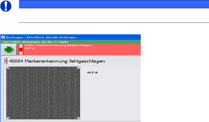
NOTICE
► Check the orientation of the inserted plate, if you see the following error message
(ACT cross cannot be measured).
Figure 4-18: Error message caused by faultily inserted plate; example SW 705