00196351-04_UM_ACT_de_en.pdf - 第124页
ACT - Accurac y Check T ool / User Manual 07/2014 Edit ion 50 Figure 4- 28 : Dialog box after setting ACT mode. Display: ACT icon The Ent er PCB d ialog box is opened ( Figur e 4- 29 ). ► Select th e ACT board. Figure 4-…
ACT - Accuracy Check Tool / User Manual 07/2014 Edition
49
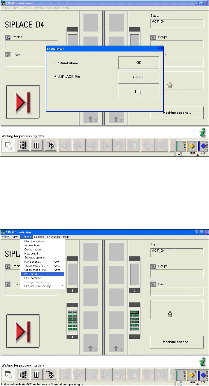
Figure 4-26: Dialog box operating mode switchover to SIPLACE Pro at the station (example SIPLACE D4)
► Press the START button on the machine.
The reference run is carried out.
► Send the recipe / job to the station with the relevant setup and the ACT placement program.
► From the Options menu, select ACT mode.
The ACT dialog box opens and the machine will automatically switch to Stand Alone mode.
Figure 4-27: Basic view of user interface for SC program (example SIPLACE D4)
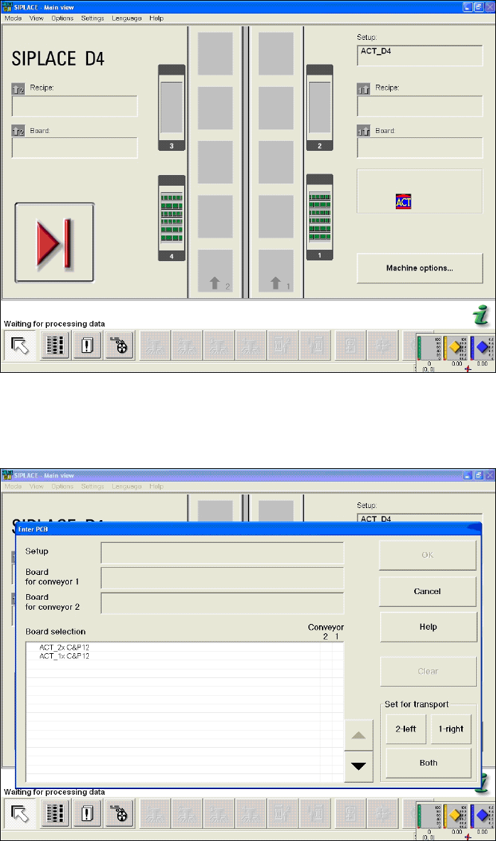
After setting ACT mode, an icon will be displayed for ACT.
ACT - Accuracy Check Tool / User Manual 07/2014 Edition
50
Figure 4-28: Dialog box after setting ACT mode. Display: ACT icon
The Enter PCB dialog box is opened (Figure 4-29).
► Select the ACT board.
Figure 4-29: Dialog box: Enter PCB (example SIPLACE D4)
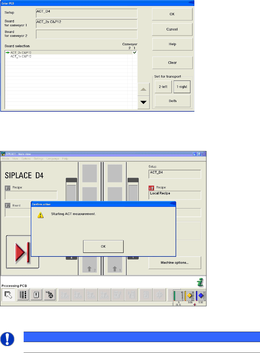
The Enter PCB dialog box is opened (Figure 4-30).
► Select the ACT board.
► Select the conveyor lane.
► Confirm your entry with OK.
ACT - Accuracy Check Tool / User Manual 07/2014 Edition
51
Figure 4-30: Dialog box: Enter PCB (example SIPLACE D4)
► Now insert the board into the input section (see also section 4.2.2).
The board gets placed and then the measurement starts automatically.
Figure 4-31: Message for ACT measurement (example SIPLACE D4)
NOTICE
The machine should not be operated during measurement!
A dialog box will open in which the current measurement operation is displayed. The fiducials that
are currently being measured are displayed.