00196351-04_UM_ACT_de_en.pdf - 第126页
ACT - Accurac y Check T ool / User Manual 07/2014 Edit ion 52 Example of meas urement operation with the ceramic componen t s Cer ampad s: Figure 4- 32 : Example of measurement window with Cerampads Example of meas ureme…
ACT - Accuracy Check Tool / User Manual 07/2014 Edition
51
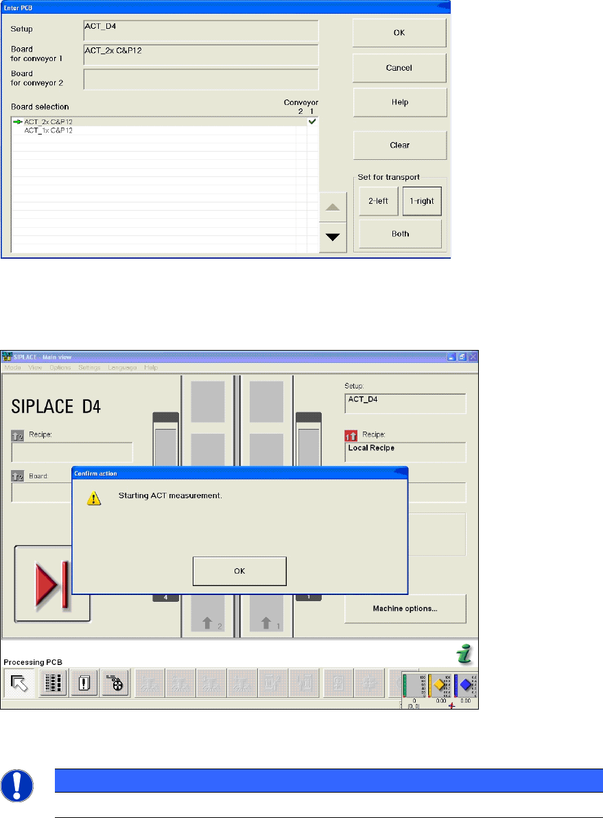
Figure 4-30: Dialog box: Enter PCB (example SIPLACE D4)
► Now insert the board into the input section (see also section 4.2.2).
The board gets placed and then the measurement starts automatically.
Figure 4-31: Message for ACT measurement (example SIPLACE D4)
NOTICE
The machine should not be operated during measurement!
A dialog box will open in which the current measurement operation is displayed. The fiducials that
are currently being measured are displayed.
ACT - Accuracy Check Tool / User Manual 07/2014 Edition
52
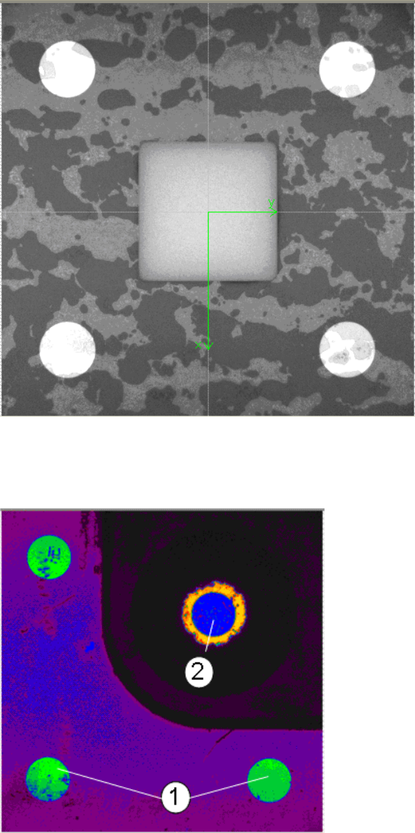
Example of measurement operation with the ceramic components Cerampads:
Figure 4-32: Example of measurement window with Cerampads
Example of measurement operation with glass components:
Figure 4-33: View of measurement window with glass components (pseudo color view)
Key:
(1) Fiducials on the ACT plate (2) Fiducials on the glass component
ACT - Accuracy Check Tool / User Manual 07/2014 Edition
53
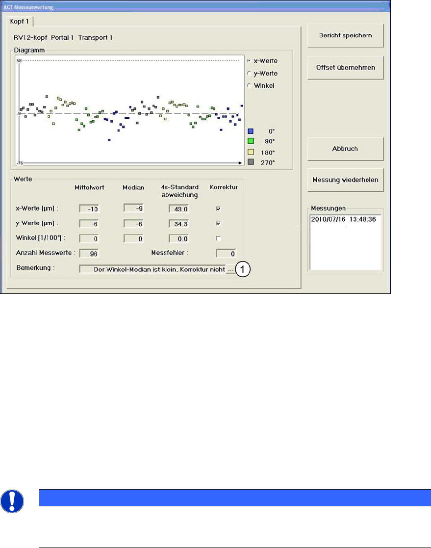
4.2.4.1 Measurement Evaluation and Measurement Data with the 605.xx Station Software
Once all fiducials have been measured, the ACT Measurement evaluation dialog box will be
automatically opened..
Example of measurement evaluation at the GUI for C&P12 heads (Cerampads) on a
SIPLACE D1:
Figure 4-34: Measurement results for ACT (example: Dialog box for C&P12 head)
Key:
(1) Here you will get additional information on the detected x-, y- and angle values
(e.g. if a correction of the offset value makes sense or not).
x-Werte (x-values)
Displays the offset values in x-direction.
y-Werte (y-values)
Displays the offset values in y-direction.
Winkel (Angle)
Displays the offset values of the placement angle.
NOTICE
When measuring the ceramic components, the placement angle cannot be calculated, as
the ceramic components are too small to deliver a reliable information for the angle.
Therefore the angle is not displayed!
The measured values are highlighted in color. This allows you to see, for instance, whether
components that were positioned with a particular placement angle show exceptionally deviations.