00198150-02_SM_TX_en.pdf - 第121页
6 Gantries 6.4 MHCU, Boards and Camera Service Manual SIPLACE TX Series 06/2017 121 Fig.153: Head interface 1 TX Fig.154: Head interface 2 TX 1. Spacer bolt M3x20 [03023427‑xx] (for VHI) 2. Spacer bolt M3x50 [03023503‑…
6 Gantries
6.4 MHCU, Boards and Camera
120 Service Manual SIPLACE TX Series 06/2017
6.4.4 Replacing the Head Interface
Parts, equipment and tools
●
Head interface TX 1 [03114439‑xx]
●
Head interface TX 2 [03116648‑xx]
●
Loctite 241 [02101037‑xx]
NOTICE
Twin head
When retrofitting your machine to TwinHead, the head interface needs to be at least at
function state -03.
Overview
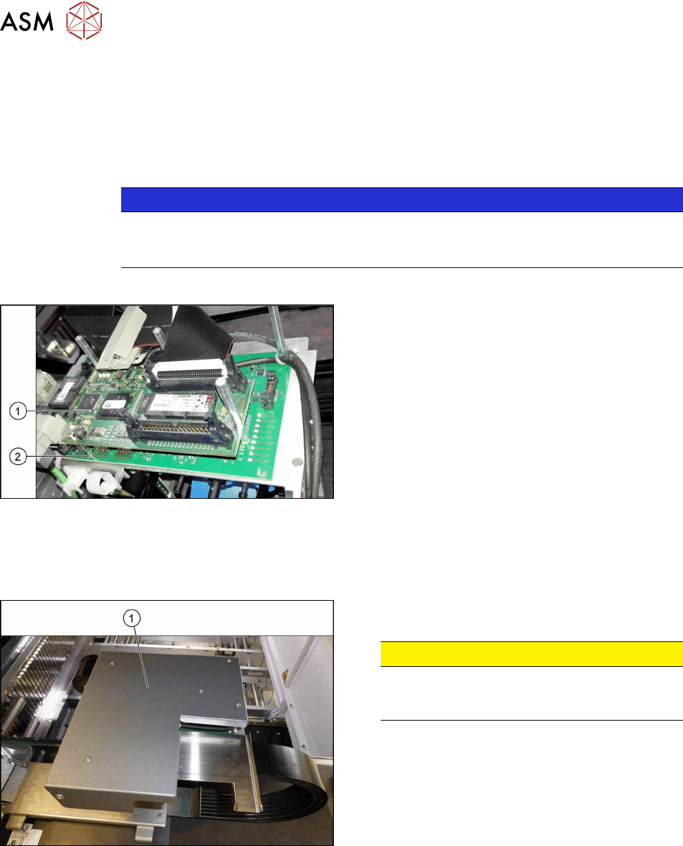
Fig.151: Boards on the gantry
1. Vision Head Interface (VHI)
2. Head interface
Removal
► Switch off the machine, disconnect it from the power supply and secure it to prevent
unauthorized reactivation. Observe the instructions in section 1.2 "Preparatory Work..." [}15].
Fig.152: Board cover
► Remove the five fastening screws and lift the
board cover(1) off.
CAUTION!
Switch off the machine
To avoid short circuits, only dismantle the cover
when the machine is switched off!
.
► Dismantle the Vision head interface. For more information about this, read section 6.4.3 "Re-
placing the Vision Head Interface (VHI) [03115454-xx]" [}117].
► Loose all connectors on the top and bottom from the head interface. Open any cable ties
where necessary. You may want to mark the positions of these connections to make clear as-
signment easier later on.
6 Gantries
6.4 MHCU, Boards and Camera
Service Manual SIPLACE TX Series 06/2017 121
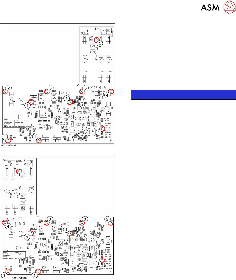
Fig.153: Head interface 1 TX
Fig.154: Head interface 2 TX
1. Spacer bolt M3x20 [03023427‑xx] (for VHI)
2. Spacer bolt M3x50 [03023503‑xx] (for cover)
3. Spacer bolt M3x15 with plastic cable clamp,
washer and screw
4. Nut M3 [03008162‑xx]
► Remove the screws and spacer bolts fastening
the head interface.
You may like to mark their positions, to make
clear assignment easier later on.
NOTICE!
Inverse layout
The layout of the two head interfaces is the
same, but inverse.
.
► Carefully remove the head interface. Make sure
that the connectors to the head adapter MHCU
are not damaged.
6 Gantries
6.4 MHCU, Boards and Camera
122 Service Manual SIPLACE TX Series 06/2017
Installation
► Follow the removal instructions in reverse order for installation. Also observe the following in-
structions:
CAUTION
Installation instructions
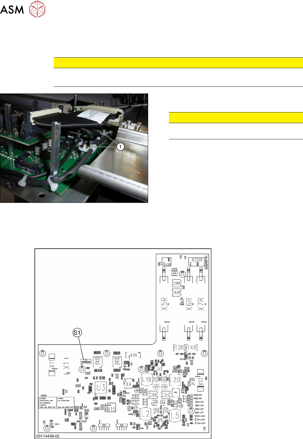
► Apply the DIP switch setting (see 6.4.4.1 "Head Interface 1/2" [}122]).
Fig.155: Securing screws
► Secure all screws with plastic cable holders(1)
with Loctite241.
CAUTION!
Do not secure screws with direct contact to
the board.
.
6.4.4.1 Head Interface 1/2
There are two head interface designs. Depending on the gantry, either the head interface 1 or 2 will
be used.
Fig.156: Head interface 1 TX