00198150-02_SM_TX_en.pdf - 第53页
3 SMPS 3.8 Replacing the AC/DC Converter Service Manual SIPLACE TX Series 06/2017 53 Fig.50: Capacitor battery ► Unplug all electrical connections (1) from the ca- pacitor battery. Mark their positions to make clear as…
3 SMPS
3.7 Replacing the Capacitor Battery Buffer Module [03103081-xx]
52 Service Manual SIPLACE TX Series 06/2017
3.7 Replacing the Capacitor Battery Buffer Module
[03103081-xx]
Parts, equipment and tools
●
Capacitor battery PCS417.381 (CAP) [03103081-xx]
Overview
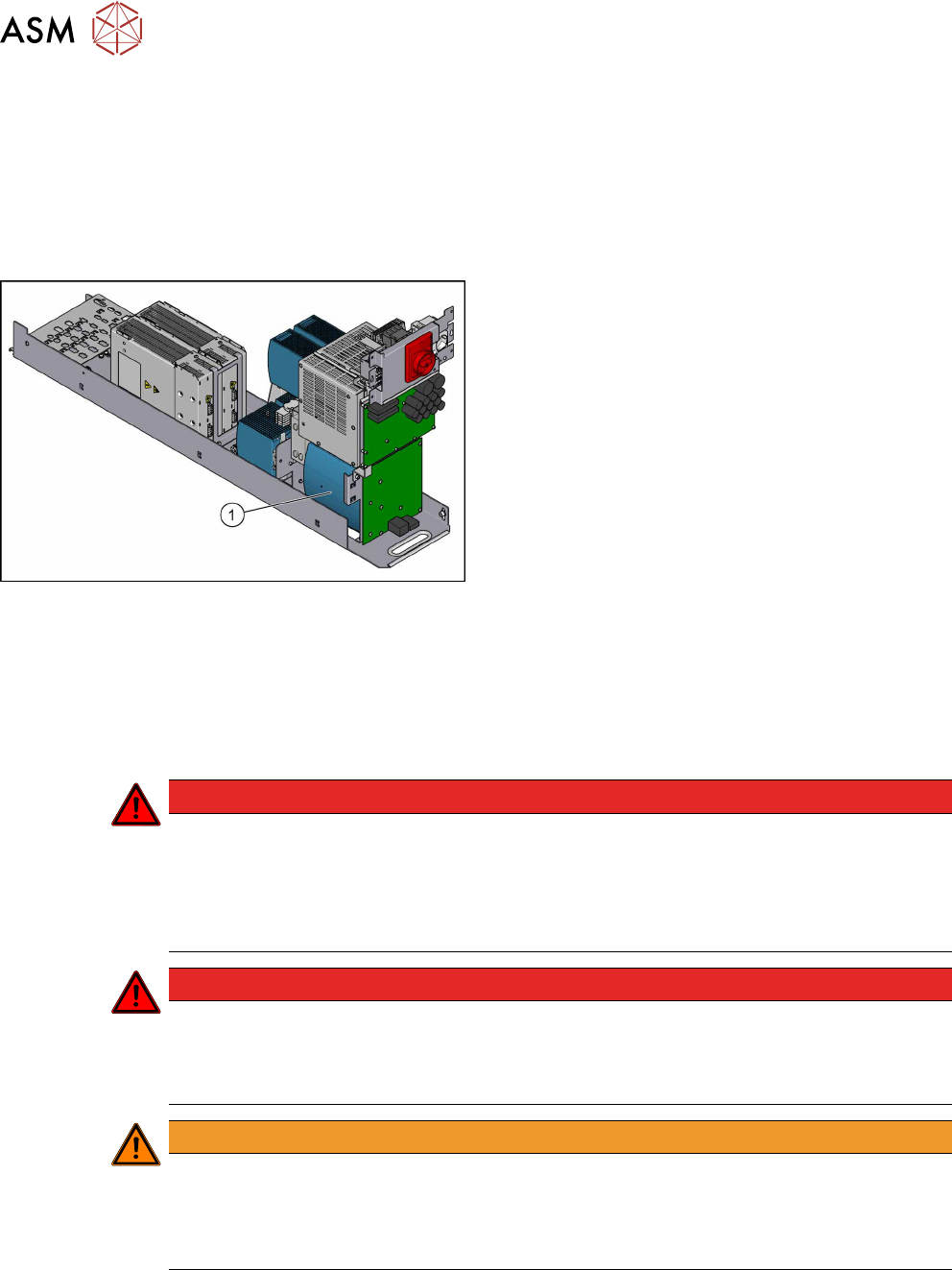
Fig.49: Capacitor battery
1. Capacitor battery
Removal
► Switch off the machine, disconnect it from the power supply and secure it to prevent
unauthorized reactivation. Observe the instructions in section 1.2 "Preparatory Work..." [}15].
► Remove the power supply fastening screw and pull out the power supply. For more informa-
tion about this read section 3.2 "Pulling out the Power Supply" [}35].
DANGER
High voltages
High DC voltages can be present in the capacitor battery.
► Observe the waiting period after power supply switch-off (5 minutes).
► Observe the LED display on the capacitor battery. This will show any residual voltages
still present.
DANGER
Checking for absence of voltage!
► Before you start working check the power supply for absence of voltage and observe
the waiting times! For more information about this read section 3.4 "Checking For Ab-
sence of Voltage" [}37].
WARNING
Carefully pull out the power supply
The power supply is not permanently fixed and can fall out of the machine.
► Pull the power supply out of the machine but not too far.
► If necessary, use suitable support e. g. a wooden beam.
► Remove contactor safety breaker. For more information about this, read section 3.6 "Repla-
cing the CSB (Contactor Safety Breaker) or the CSB Cover" [}49].
3 SMPS
3.8 Replacing the AC/DC Converter
Service Manual SIPLACE TX Series 06/2017 53
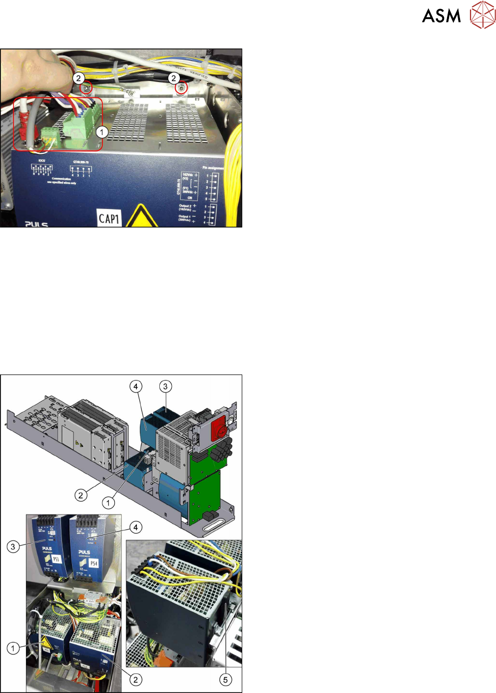
Fig.50: Capacitor battery
► Unplug all electrical connections(1) from the ca-
pacitor battery. Mark their positions to make clear
assignment easier later on.
► Remove the fastening screws(2).
► Lift the capacitor battery off the rail.
Installation
► Follow the removal instructions in reverse order for installation.
3.8 Replacing the AC/DC Converter
Parts, equipment and tools
●
Voltage measuring device
Select the required AC/DC converter:
Fig.51: Overview of the AC/DC converters
1. PS1: AC/DC converter DC300/150 VDC 1.3kW
3phase [03103087‑xx]
→ Set to 300/160 V for MGCU and MHCU
2. PS2: AC/DC converter 36V 26.7A 960W 3 phase
[03103331‑xx]
→ Set to 42 V for MHCU, conveyor system, illu-
mination
3. PS3: AC/DC converter DC24V/40A 3 phase
[03102840‑xx]
→ Set to 28 V for FCU
4. PS4: AC/DC converter DC24V/20A 3 phase
[03055232‑xx]
→ Set to 24 V for power fail, safety circuit SSK,
tape cutter, PCB handling
The power fail signal is generated by the AC/DC
converter A5 and sent to the MGCU and MHCU.
5. Unlock handle
3 SMPS
3.8 Replacing the AC/DC Converter
54 Service Manual SIPLACE TX Series 06/2017
Removal
► Switch off the machine, disconnect it from the power supply and secure it to prevent
unauthorized reactivation. Observe the instructions in section 1.2 "Preparatory Work..." [}15].
► Remove the power supply fastening screw and pull out the power supply. For more informa-
tion about this read section 3.2 "Pulling out the Power Supply" [}35].
DANGER
Checking for absence of voltage!
► Before you start working check the power supply for absence of voltage and observe
the waiting times! For more information about this read section 3.4 "Checking For Ab-
sence of Voltage" [}37].
► Unplug all electrical connections from the AC/DC converter. Mark their positions to make clear
assignment easier later on.
► Push the unlock handle and tilt this slightly upwards. Now take the AC/DC converter up and
off.
Installation
► Follow the removal instructions in reverse order for installation. Also observe the following in-
structions:
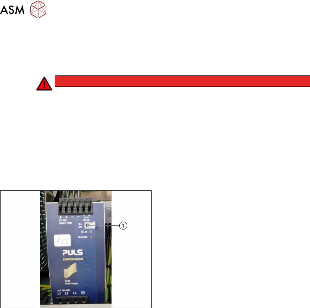
Fig.52: Setting screw
Setting the voltage:
► Open the protective cap on the setting screw(1).
► Use a slotted screwdriver to set the correct
voltage on the AC/DC converter.
Check the voltage with a suitable voltage meas-
uring device between the terminals + and–.