00198150-02_SM_TX_en.pdf - 第48页
3 SMPS 3.5 MGCUs 48 Service Manual SIPLACE TX Series 06/2017 3.5.4 Replacing the MGCU Fan [03104136-xx] Parts, equipment and tools ● Fan for MGCU [03104136-xx] Overview Fig.43: MGCU fans 1. Three fans on the MGCU 2. Ele…
3 SMPS
3.5 MGCUs
Service Manual SIPLACE TX Series 06/2017 47
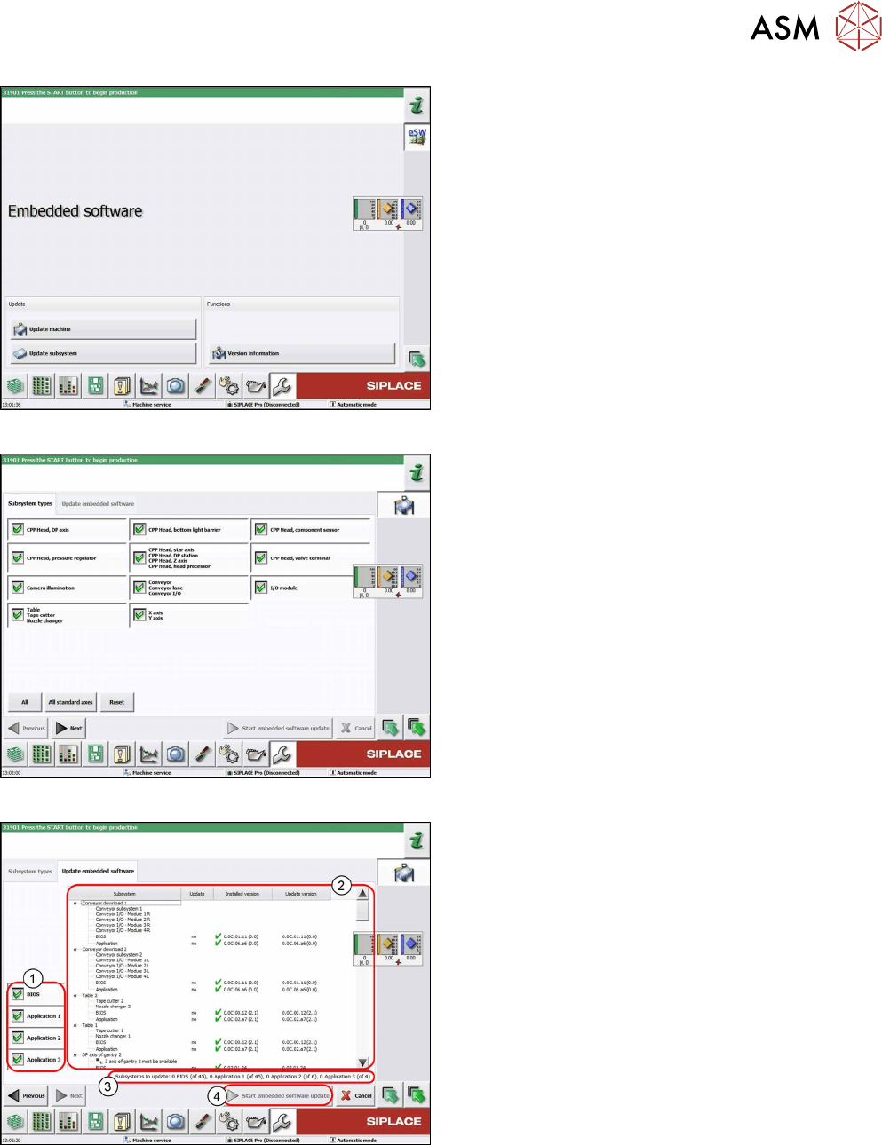
Fig.40: Embedded software menu
Select the required function:
► Click on Update machine… to check the entire
machine and to perform an eSW download for
multiple subsystems (see next picture).
► Click on Update subsystem… to select and
check one subsystem and to perform an eSW
download.
► Click on the button Version information…, to
view all versions of the subsystems, BIOS, ap-
plication 1/2/3/5.
Fig.41: Select subsystem
► Select the subsystem for the eSW download.
► Click on the Continue button.
Fig.42: Update machine menu
1. Selection buttons:
BIOS
Application 1
Application 2
Application 3
2. Shows the status of the individual subsystems
3. Update information
This shows you the number of subsystems which
still need to be downloaded.
4. Starts the download
3 SMPS
3.5 MGCUs
48 Service Manual SIPLACE TX Series 06/2017
3.5.4 Replacing the MGCU Fan [03104136-xx]
Parts, equipment and tools
●
Fan for MGCU [03104136-xx]
Overview
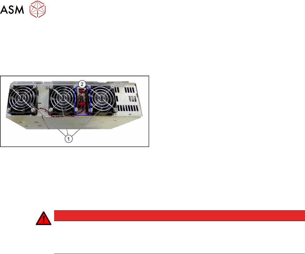
Fig.43: MGCU fans
1. Three fans on the MGCU
2. Electrical connections of the fans
Removal
► Switch off the machine, disconnect it from the power supply and secure it to prevent
unauthorized reactivation. Observe the instructions in section 1.2 "Preparatory Work..." [}15].
► Remove the power supply fastening screw and pull out the power supply. For more informa-
tion about this read section 3.2 "Pulling out the Power Supply" [}35].
DANGER
Checking for absence of voltage!
► Before you start working check the power supply for absence of voltage and observe
the waiting times! For more information about this read section 3.4 "Checking For Ab-
sence of Voltage" [}37].
► Dismantle and remove the MGCU from the SMPS holder (see 3.5.2 "Replacing MGCU
[03117531Sxx]" [}45]).
► Unplug the electrical connection to the fan. You may want to mark the position of this connec-
tion to make clear assignment easier later on.
► Remove the four screws fastening the fan and then remove the fan.
Installation
► Follow the removal instructions in reverse order for installation.
3 SMPS
3.6 Replacing the CSB (Contactor Safety Breaker) or the CSB Cover
Service Manual SIPLACE TX Series 06/2017 49
3.6 Replacing the CSB (Contactor Safety Breaker) or the CSB
Cover
DANGER
High voltages
High DC voltages can be present in the CSB.
► No parts of the CSB may be replaced.
► Only the front cover of the CSB may be dismantled for connecting cables or removing
the complete unit.
► The CSB may only be replaced as a complete unit.
Parts, equipment and tools
Choose the required spare part:
●
Contactor safety breaker [03112066‑xx]
●
Board cover assembly [03116600-xx]
Removal
► Switch off the machine, disconnect it from the power supply and secure it to prevent
unauthorized reactivation. Observe the instructions in section 1.2 "Preparatory Work..." [}15].
► Remove the power supply fastening screw and pull out the power supply. For more informa-
tion about this read section 3.2 "Pulling out the Power Supply" [}35].
DANGER
Checking for absence of voltage!
► Before you start working check the power supply for absence of voltage and observe
the waiting times! For more information about this read section 3.4 "Checking For Ab-
sence of Voltage" [}37].
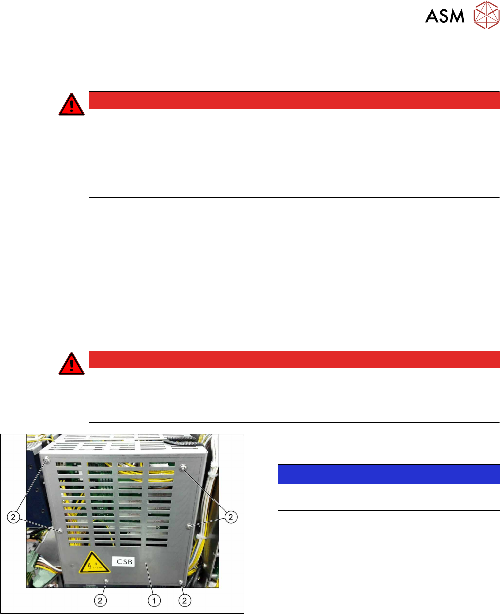
Fig.44: Removing the cover
► Remove the six screws(2) fastening the
cover(1).
NOTICE!
If you are replacing only the CSB cover you can
end removal here and continue with installation.
.