00198150-02_SM_TX_en.pdf - 第35页
3 SMPS 3.2 Pulling out the Power Supply Service Manual SIPLACE TX Series 06/2017 35 3.2 Pulling out the Power Supply Fig.23: Leg support For some service tasks it is necessary to pull the power supply out of the machine…
3 SMPS
3.1 SMPS - Overview
34 Service Manual SIPLACE TX Series 06/2017
3.1 SMPS - Overview
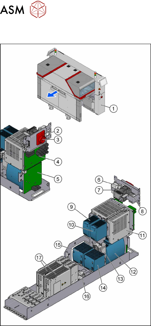
Fig.22: Overview of the SMPS
1. The SMPS is located behind the right cover at
location2.
2. Service socket
3. Main power switch [03125553‑xx]
4. Fuse and distributor PCB (FD.A1) [03121508‑xx]
3.9 "Replacing the Distribution and Fusing
Assembly" [}55]
5. Distributor assembly TX (I/O control unit)
[03121427‑xx]
3.10 "Replacing the Distributor Assembly
[03121427‑xx]" [}57]
6. Circuit breaker 5SY4 1-POLE 10A C
[03098363‑xx]
7. Power supply 24V/1.3A pulse ML30.241
[03112748‑xx]
3.11 "Replacing the Interior Illumination Power
Supply [03112748-xx]" [}59]
8. K1, Protective contactor combination
[03114295‑xx]
9. AC/DC-Converter DC24V/20A 3-PHASE
[03055232‑xx]
3.8 "Replacing the AC/DC Converter" [}53]
10. AC/DC-Converter DC24V/20A 3-PHASE
[03055232‑xx]
3.8 "Replacing the AC/DC Converter" [}53]
11. Contactor safety breaker (CSB) SMPS
[03112066Sxx]
3.6 "Replacing the CSB (Contactor Safety
Breaker) or the CSB Cover" [}49]
12. Buffer module PCS417.381(CAP) [03103081‑xx]
3.7 "Replacing the Capacitor Battery Buffer Mod-
ule [03103081-xx]" [}52]
13. CAN interface CINX [03108598-xx]
3.12 "Replacing the CAN Interface CINX
[03108598‑xx]" [}61]
14. Pulse unit 4-fold TX (42VDC) [03123989‑xx]
3.8 "Replacing the AC/DC Converter" [}53]
15. AC/DC-Converter DC300/150V 1.3KW 3-PHASE
[03103087‑xx]
3.8 "Replacing the AC/DC Converter" [}53]
16. Measuring points for absence of voltage 2x300 V
DC and ground
3.4 "Checking For Absence of Voltage" [}37]
17. Position controller gantry axes MGCU-2
[03117531Sxx]
3.5 "MGCUs" [}43]
3 SMPS
3.2 Pulling out the Power Supply
Service Manual SIPLACE TX Series 06/2017 35
3.2 Pulling out the Power Supply
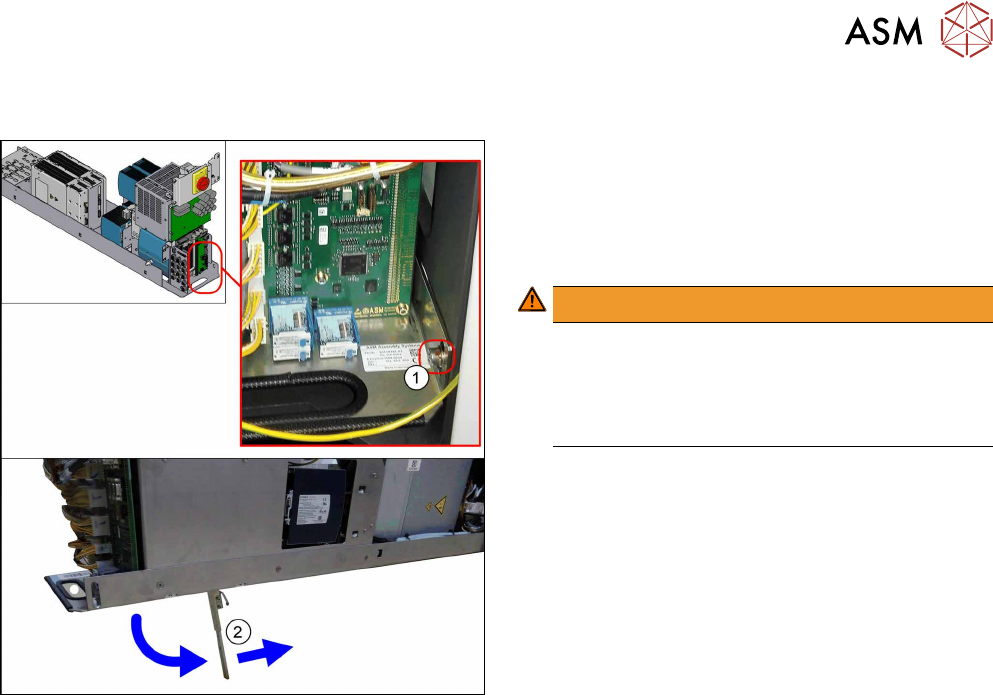
Fig.23: Leg support
For some service tasks it is necessary to pull the
power supply out of the machine.
► Remove the screw (1) fastening the power sup-
ply.
► Pull the power supply out as far as necessary.
WARNING!
The power supply could fall down without the leg
support(2).
For secure positioning, make sure that the bot-
tom of the leg support points towards the
machine.
.
3 SMPS
3.3 Electrical Checks
36 Service Manual SIPLACE TX Series 06/2017
3.3 Electrical Checks
DANGER
Observe the safety instructions
There is a risk of dangerous touch voltages and short circuits occurring in power supplies
which have been made accessible and are connected for measurement purposes.
Nonobservance of these safety instructions may cause injury to personnel and dam-
age to the machine!
Measurements may only be performed by specially trained service technicians with appro-
priate qualifications and expertise.
► Observe the safety instructions in this manual and in the user manual.
Tools and Equipment required
●
Digital voltmeter, class 1,5
●
Test cable with test probes or terminals
CAUTION
Take care not to damage the supply lines!
Make sure that the main power cable and supply cables in the machine are not trapped and
that the insulation is not damaged.
Preparation
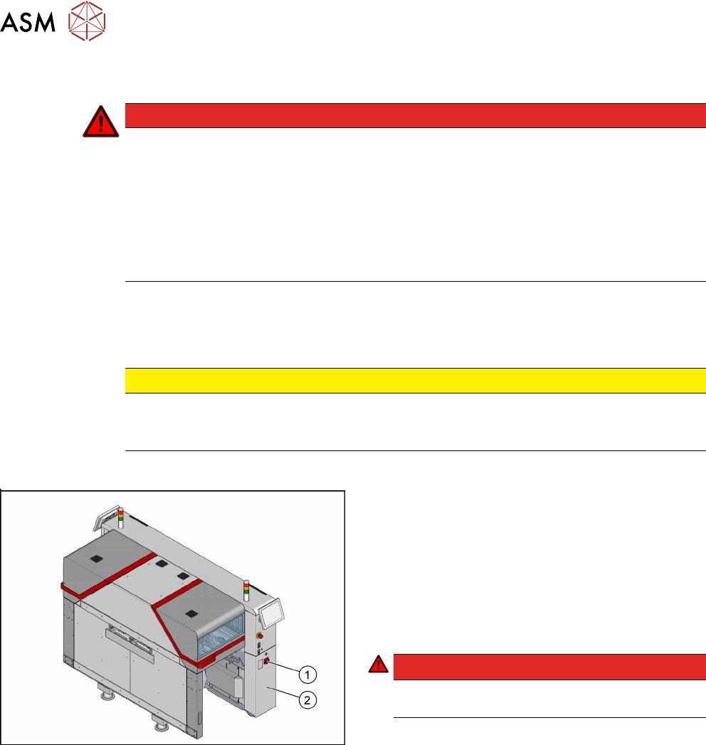
Fig.24: Main switch
► End all placement operations and switch the
machine off at the main switch(1).
► Disconnect the machine from the main power
supply.
► Open the lock on the power supply cover(2).
► Pull the power supply out towards the front
(see 3.2 "Pulling out the Power Supply" [} 35]).
► Reconnect the machine to the power supply.
DANGER!
Careful: There may be dangerous touch voltages
in the vicinity of the open power supply!
.
► Switch the machine on again at the main switch
and start it up.
Voltages
► Measure the required voltages.
Please refer to the relevant circuit diagram for your machine for details of the various voltages.
●
Detailed circuit diagrams folder for SIPLACE TX-Series (up to no. 499) [DE+EN: 00197933-
xx]
●
Detailed circuit diagrams folder for SIPLACE TX-Series (from no. 500) [DE+EN: 00198274-xx]