00198150-02_SM_TX_en.pdf - 第41页
3 SMPS 3.4 Checking For Absence of Voltage Service Manual SIPLACE TX Series 06/2017 41 The following figure explains the LED status of the PS1 power pack (300 VDC): Fig.30: LED status PS1-PS2 300VDC Monitoring the volt…
3 SMPS
3.4 Checking For Absence of Voltage
40 Service Manual SIPLACE TX Series 06/2017
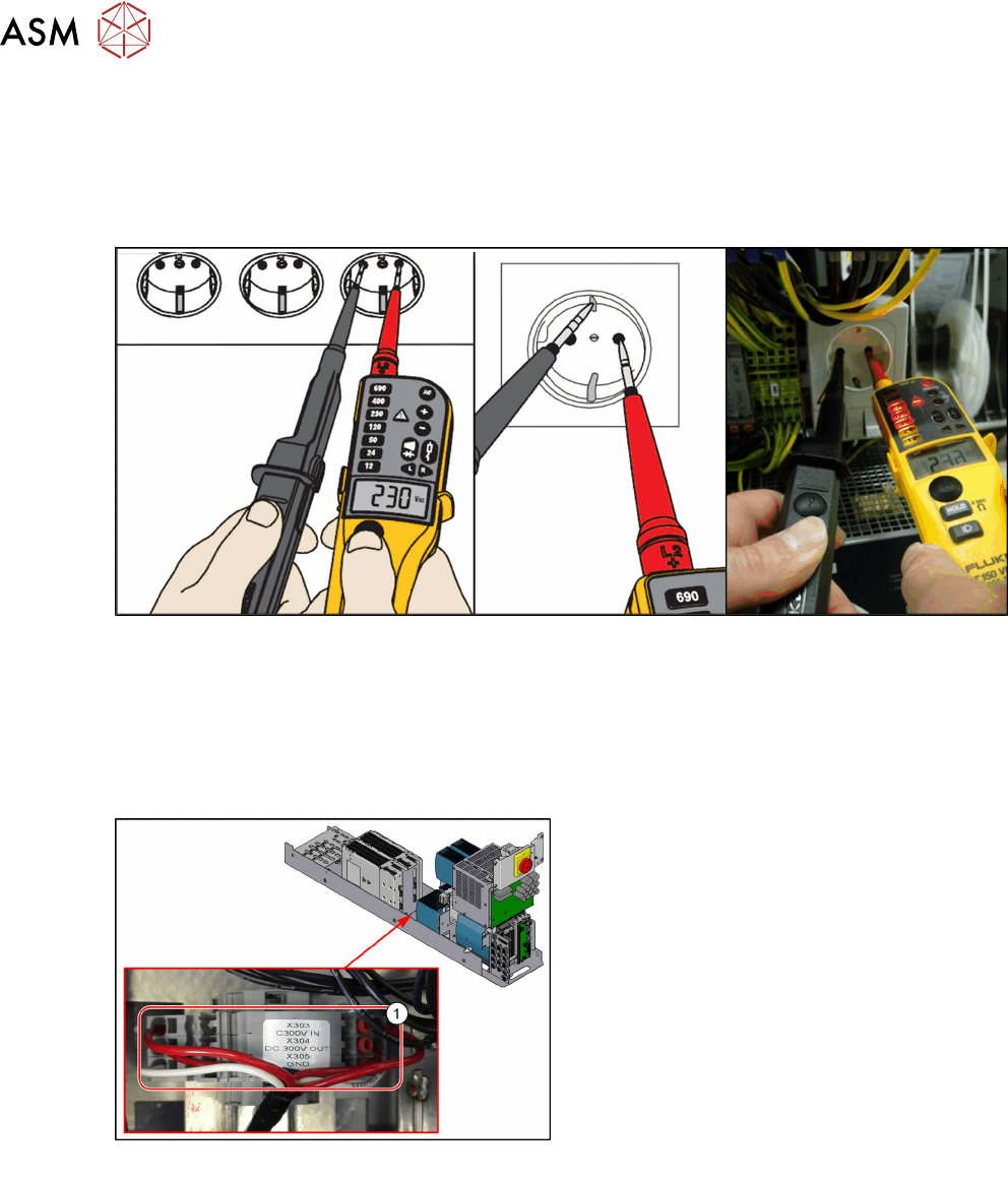
Measurement with known reference voltage
To conclude the self-test, check the voltage tester with a known reference voltage.
You can use the service socket on the power supplier (disabled with "110V option") or any other
electrical socket.
Measure the voltage present between the pins and at PE (ground).
Fig.28: Test with reference voltage
Measuring the voltage absence directly after switching machine off
When the machine has been switched off, the full voltage is still present at the measurement points
X303 (in) and X304 (out).
Measurement is always performed at the reference point X305 (GND)!
► Pull the power supply out towards the front (see 3.2 "Pulling out the Power Supply" [}35]).
Fig.29: Measuring points
1. Measuring points at power supply
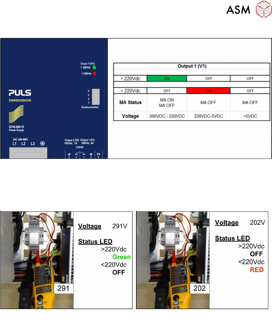
Test 300V IN_X303-X305:
Currently present voltage
Test 300V OUT_X304-X305:
LED display Output 1 at AC/DC converter
Green: Voltage over 220V
The power pack shows an LED display for out-
put 1 > 220 V in green, which means that the
voltage is still over 220 V!
3 SMPS
3.4 Checking For Absence of Voltage
Service Manual SIPLACE TX Series 06/2017 41
The following figure explains the LED status of the PS1 power pack (300 VDC):
Fig.30: LED status PS1-PS2 300VDC
Monitoring the voltage absence after switch-off
The voltage at the measurement points X303 (IN PS1/PS2) and X304 (OUT CAP) only discharges
slowly.
After switch-off, the voltage drops from 300VDC to under 5VDC in approx. five minutes.
Fig.31: Measuring voltage
As soon as the voltage has undershot a value of 220VDC, the LED display on the power pack
changes!
3 SMPS
3.4 Checking For Absence of Voltage
42 Service Manual SIPLACE TX Series 06/2017
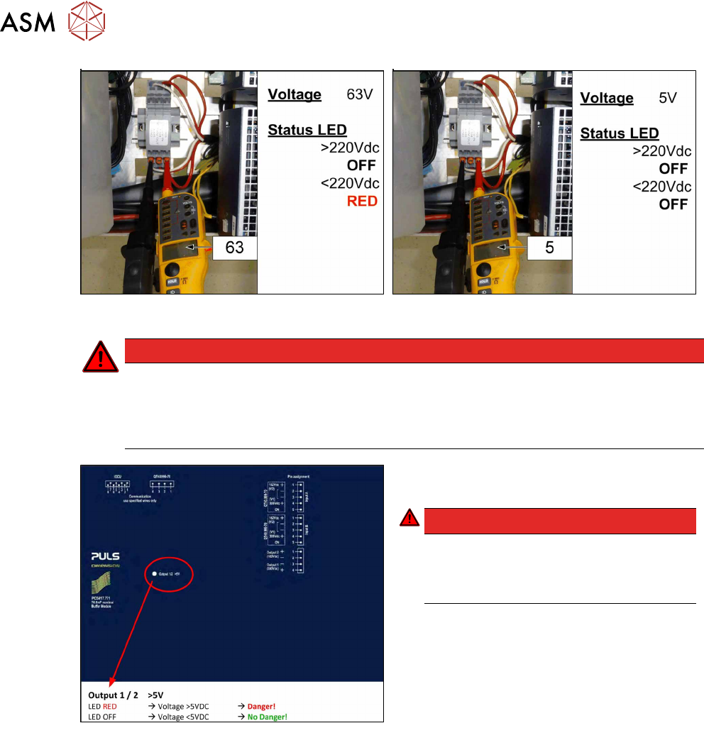
Fig.32: Measuring voltage
DANGER
Measurement values below 5VDC
Measure between the following points:
► X303 (IN) – X305 (GND) < 5VDC
► X304 (OUT) – X305 (GND) < 5VDC
Fig.33: LED on the capacitor battery(CAP)
► Check the LED on the capacitor battery
(CAP).
DANGER!
Once the LED on the capacitor battery
(CAP) does not light any longer, it is pos-
sible to work on the power supply without
hazard!
.