00198150-02_SM_TX_en.pdf - 第181页
7 Conveyor 7.7 Boards Service Manual SIPLACE TX Series 06/2017 181 7.7 Boards 7.7.1 Replacing the Conveyor Control TSP420 [03087642-xx] Parts, equipment and tools ● Conveyor control TSP420 assembly [03087642-xx] Overview…
7 Conveyor
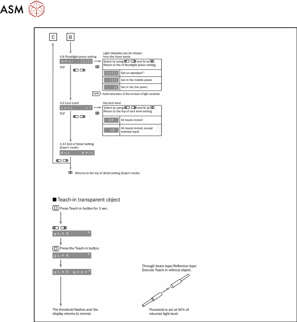
7.6 Fiber Optic Cable and Light Barriers
180 Service Manual SIPLACE TX Series 06/2017
Fig.241: Setting the fiber optic cable sensor - 4
7 Conveyor
7.7 Boards
Service Manual SIPLACE TX Series 06/2017 181
7.7 Boards
7.7.1 Replacing the Conveyor Control TSP420 [03087642-xx]
Parts, equipment and tools
●
Conveyor control TSP420 assembly [03087642-xx]
Overview
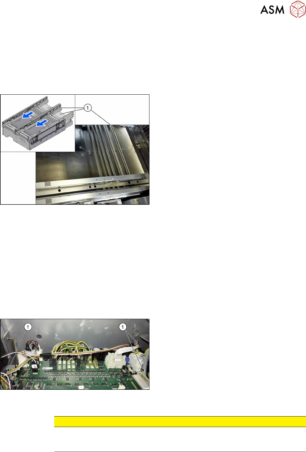
Fig.242: Covers
The conveyor control units are located under the cov-
ers(1) in the input conveyor.
Two TSP420s are fitted on dual conveyors.
For an overview of the connectors, switches etc. of the
TSP420, refer to section 7.7.1.1 "Conveyor Control
TSP420 [03087642-xx]" [}182].
Removal
► Use the software or manually move the conveyor rail into a position which allows you best ac-
cess.
– To move the conveyor rail manually, pull the toothed belt of the width adjustment unit.
► Switch off the machine, disconnect it from the power supply and secure it to prevent
unauthorized reactivation. Observe the instructions in section 1.2 "Preparatory Work..." [}15].
► Move all gantries out of the transport area as far as possible at one side of the machine.
► Remove the spacer bolts fastening the cover plate above the conveyor control and remove
the cover plate.
► Unplug all electrical connections to the conveyor control. If necessary, mark their positions to
make clear assignment easier later on.
Fig.243: Spacer bolts
► Loosen the four spacer bolts(1).
► Remove the conveyor control together with the mounting plate from the machine.
CAUTION
Do not remove the conveyor control from the mounting plate.
The conveyor control may not be removed from the mounting plate because the mounting
plate serves as a cooling element for the conveyor control.
7 Conveyor
7.7 Boards
182 Service Manual SIPLACE TX Series 06/2017
Installation
► Follow the removal instructions in reverse order for installation. Also observe the following in-
structions:
CAUTION
Installation instructions
► Check the embedded software and perform a download if needed (see 7.7.2 "eSW
Download (SW 70x)" [}186]).
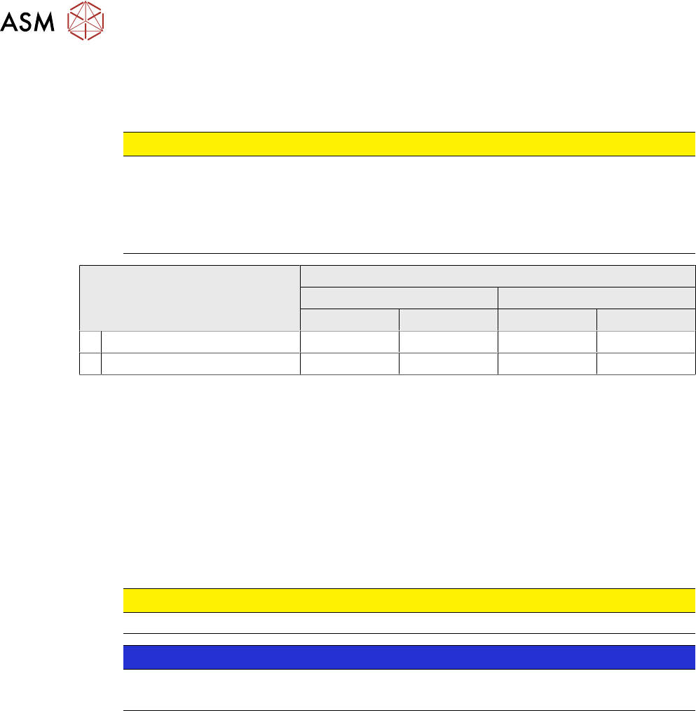
► Check the jumper setting: jumper 1 and 2 must be set correctly for both TSP420 (see
table).
Jumper Setting for machine
Up to serial no. TA500 Serial no. TA500 or later
Lane 1 Lane 2 Lane 1 Lane 2
1 For MCAN 2-3 1-2 2-3 2-3
2 For internal CAN 1-2 1-2 1-2 1-2
See also: 7.7.1.1 "Conveyor Control TSP420 [03087642-xx]" [}182]
See also
2 eSW Download (SW 70x) [}186]
7.7.1.1 Conveyor Control TSP420 [03087642-xx]
Two TSP420 are fitted in SIPLACE TX-Series machines.
The conveyor control "TSP420 assembly" [03087642-xx] comprises the following components:
●
Main board: TSP420-M [ 03087640-xx ]
●
I/O board: TSP420-IO [ 03087641-xx ]
CAUTION
These two boards may not be separated!
NOTICE
Terminating resistor (cable set PCB dual conveyor [03110653‑xx])
The terminating resistor is set for the "Shuttle Option" by default.