00198150-02_SM_TX_en.pdf - 第95页
6 Gantries 6.2 X and Y Axis Service Manual SIPLACE TX Series 06/2017 95 Installation Check Fig.105: X drive (using example of X-Series) 1. X motor plate 2. Guide trolley 3. 0.5mm gap between motor plate and top edge of…
6 Gantries
6.2 X and Y Axis
94 Service Manual SIPLACE TX Series 06/2017
Installation
► Follow the removal instructions in reverse order for installation. Also observe the following in-
structions:
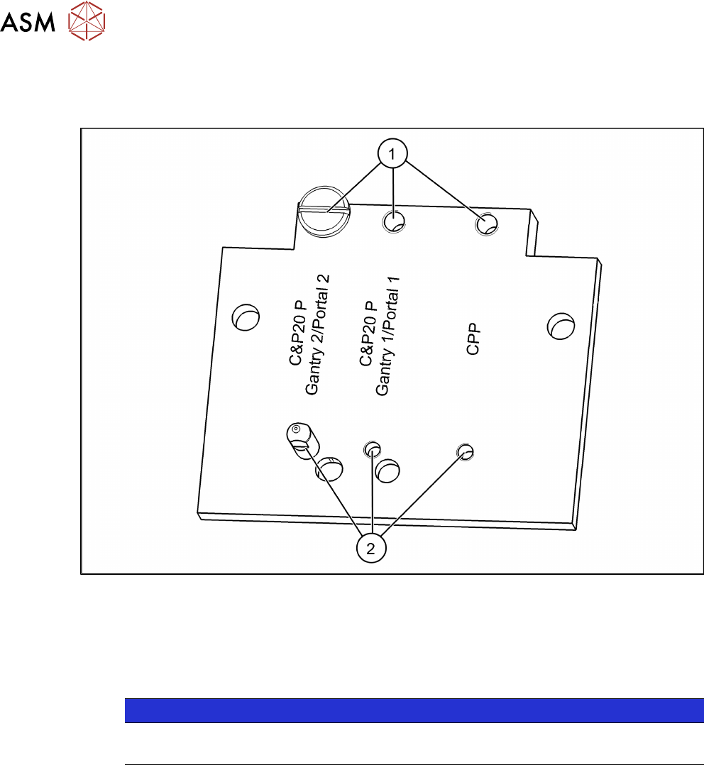
Fig.104: Setting the head suspension
► Position the screws(1) and (2) in relation to the head and the gantry.
See also
2 Replacing the SIPLACE C&P20 P/M2 Head [}202]
2 Replacing the SIPLACE CPP/M Head [}206]
6.2.10 Installation Check for X Motor Plate
NOTICE
SIPLACE Service
This task may only be performed by SIPLACE service technicians.
6 Gantries
6.2 X and Y Axis
Service Manual SIPLACE TX Series 06/2017 95
Installation Check
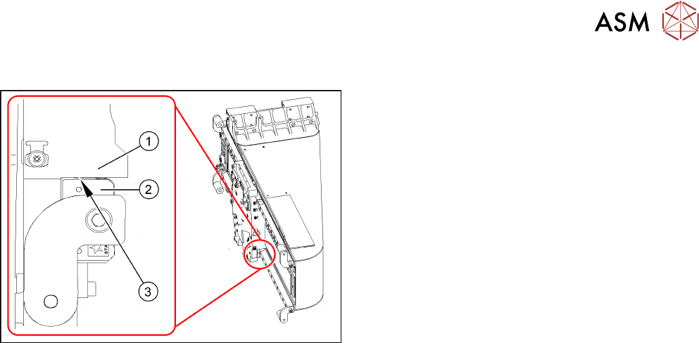
Fig.105: X drive (using example of X-Series)
1. X motor plate
2. Guide trolley
3. 0.5mm gap between motor plate and top edge of
linear guide
► When installing the X motor plate, place a feeler
gauge(3) of 0.5mm between the X motor plate
and guide trolley.
► If the distance is too low, remove the X drive and
fit it again.
6 Gantries
6.3 Trailing Cable and Printed Circuit Boards
96 Service Manual SIPLACE TX Series 06/2017
6.3 Trailing Cable and Printed Circuit Boards
6.3.1 Gantries – Trailing Cables and Boards – Overview
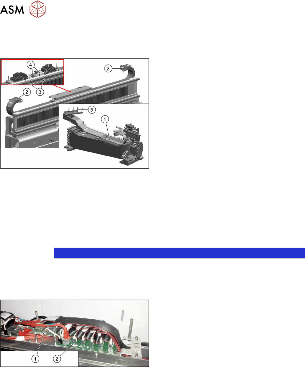
Fig.106: Trailing cables and boards
1. X axis trailing cable
6.3.6.1 "Replacing the X Axis Trailing
Cable" [}103]
2. Y axis trailing cable
6.3.6.2 "Replacing the Y Axis Trailing
Cable" [}108]
3. Trailing cable interface
6.3.2 "Replacing the Trailing Cable Inter-
face" [}96]
4. Vision base interface (VBI)
6.3.3 "Replacing the Vision Base Interface (VBI)
[03115474-xx]" [}98]
5. Gantry interface (mounting position)
6.3.4 "Replacing the Gantry Interface" [}99]
●
6.3.5 "Handling the Hose Unlocking Tool
[03047090-xx]" [}102]
6.3.2 Replacing the Trailing Cable Interface
Parts, equipment and tools
●
Trailing interface 1 [03115810-xx]
●
Trailing interface 2 [03115814-xx]
NOTICE
SIPLACE TX micron machines
The functionality level of the trailing cable interface must be at least -02 for SIPLACE TX
micron machines.
Overview
Fig.107: Vision base interface and trailing cable interface
1. Vision base interface (VBI)
2. Trailing cable interface