00198150-02_SM_TX_en.pdf - 第60页
3 SMPS 3.11 Replacing the Interior Illumination Power Supply [03112748-xx] 60 Service Manual SIPLACE TX Series 06/2017 Fig.62: Electrical connections ► Unplug the electrical connections (2) from the power pack PS5. You…
3 SMPS
3.11 Replacing the Interior Illumination Power Supply [03112748-xx]
Service Manual SIPLACE TX Series 06/2017 59
3.11 Replacing the Interior Illumination Power Supply
[03112748-xx]
Parts, equipment and tools
●
Power supply 24V/1.3A pulse ML30.241 [03112748-xx]
Overview
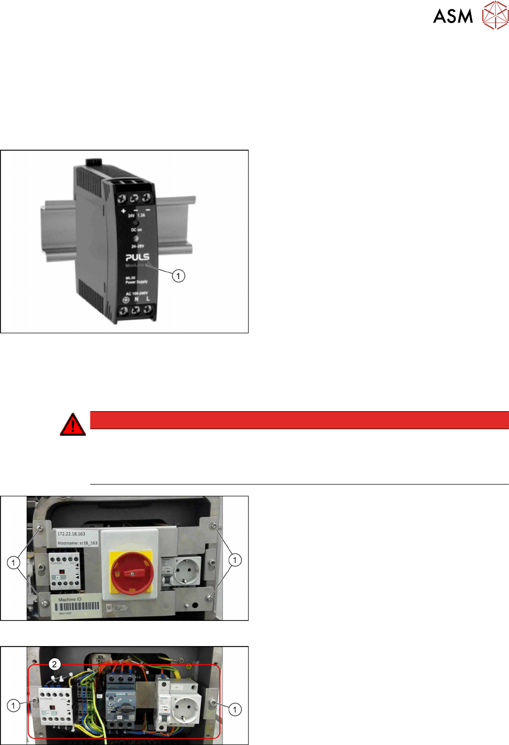
Fig.59: Power supply
1. Power supply
Removal
► Switch off the machine, disconnect it from the power supply and secure it to prevent
unauthorized reactivation. Observe the instructions in section 1.2 "Preparatory Work..." [}15].
DANGER
Checking for absence of voltage!
► Before you start working check the power supply for absence of voltage and observe
the waiting times! For more information about this read section 3.4 "Checking For Ab-
sence of Voltage" [}37].
Fig.60: Main switch cover plate
► Remove the four screws(1) fastening the main
switch cover plate.
► Remove the main switch cover plate.
Fig.61: Main switch assembly
► Loosen the two screws(1) fastening the main
switch assembly.
► Remove the main switch assembly(2).
3 SMPS
3.11 Replacing the Interior Illumination Power Supply [03112748-xx]
60 Service Manual SIPLACE TX Series 06/2017
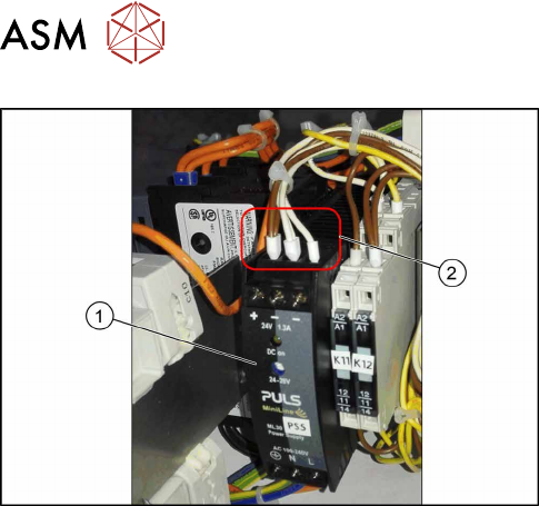
Fig.62: Electrical connections
► Unplug the electrical connections(2) from the
power pack PS5. You may want to mark their po-
sitions for easier replacement later on.
► Push the unlock handle on the back of the power
supply and remove the power supply(1).
Installation
► Follow the removal instructions in reverse order for installation.
3 SMPS
3.12 Replacing the CAN Interface CINX [03108598‑xx]
Service Manual SIPLACE TX Series 06/2017 61
3.12 Replacing the CAN Interface CINX [03108598‑xx]
Parts, equipment and tools
●
CAN interface CINX [03108598-xx]
Overview
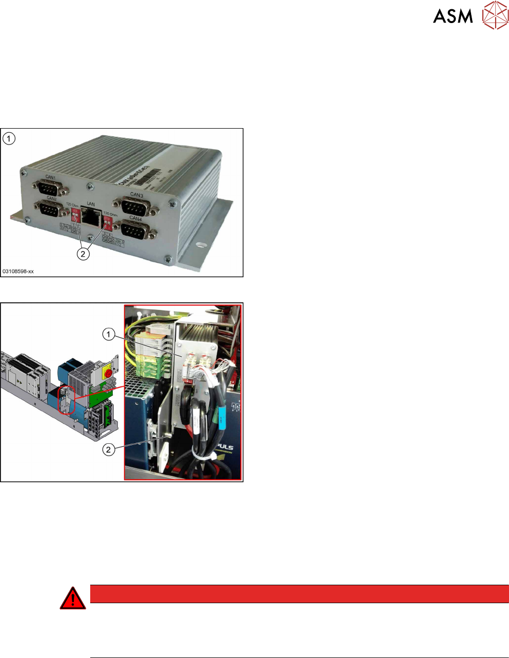
Fig.63: CAN interface CINX
1. CAN interface CINX [03108598-xx]
2. DIP switches
Fig.64: CAN interface CINX on SMPS
1. CAN interface CINX
2. Fastening screw
The CAN interface CINX is located at the side of the
power supply.
Removal
► Switch off the machine, disconnect it from the power supply and secure it to prevent
unauthorized reactivation. Observe the instructions in section 1.2 "Preparatory Work..." [}15].
► Remove the power supply fastening screw and pull out the power supply. For more informa-
tion about this read section 3.2 "Pulling out the Power Supply" [}35].
DANGER
Checking for absence of voltage!
► Before you start working check the power supply for absence of voltage and observe
the waiting times! For more information about this read section 3.4 "Checking For Ab-
sence of Voltage" [}37].
► Remove the screw fastening the CAN interface CINX.
► Unplug all electrical connections (3x CAN bus, 1x network). Mark their positions to make clear
assignment easier later on.
► Take the CAN interface CINX out of the machine.
Installation
► Set the four DIP switches to OFF.
► Follow the removal instructions in reverse order for further installation.