00198150-02_SM_TX_en.pdf - 第28页
2 Basic Machine 2.4 Replacing the Cover 28 Service Manual SIPLACE TX Series 06/2017 2.4 Replacing the Cover Parts, equipment and tools ● Choose the required part: – Cover, long – location 1 TX [03118640‑xx] – Cover, shor…
2 Basic Machine
2.3 Replacing the Swivel Head [03006436-xx]
Service Manual SIPLACE TX Series 06/2017 27
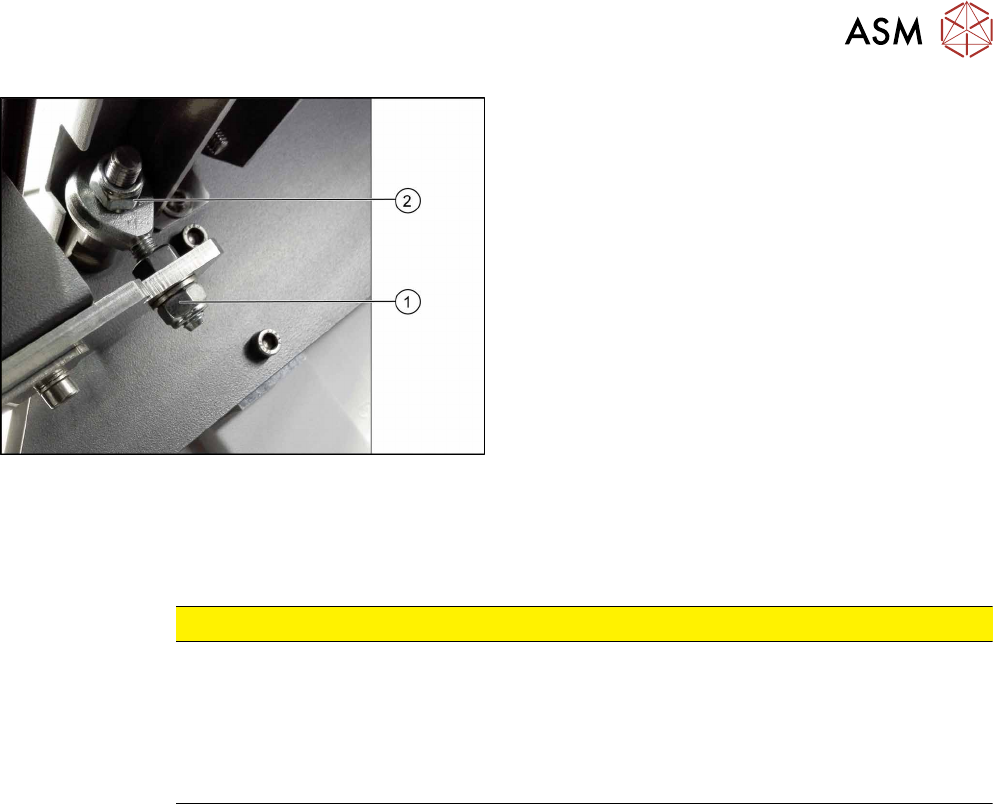
Fig.13: Removing the swivel head
► Close the cover.
► Remove the nut (1).
► Remove the cover from the machine.
► Remove the nut (2).
► Remove the swivel head.
Installation
► Follow the removal instructions in reverse order for installation. Also observe the following in-
structions:
CAUTION
Installation instructions
► If the nuts are not self-locking, secure them with Loctite241.
► Set the nut(1).
Make sure that the cover can move freely for opening and closing.
Make sure that the cover is not distorted.
See also: 2.4.1 "Setting the Covers" [}30]
2 Basic Machine
2.4 Replacing the Cover
28 Service Manual SIPLACE TX Series 06/2017
2.4 Replacing the Cover
Parts, equipment and tools
●
Choose the required part:
– Cover, long – location 1 TX [03118640‑xx]
– Cover, short – location 1 TX [03118601‑xx]
– Cover – location 2 [03117921-xx]
●
Second person
Overview
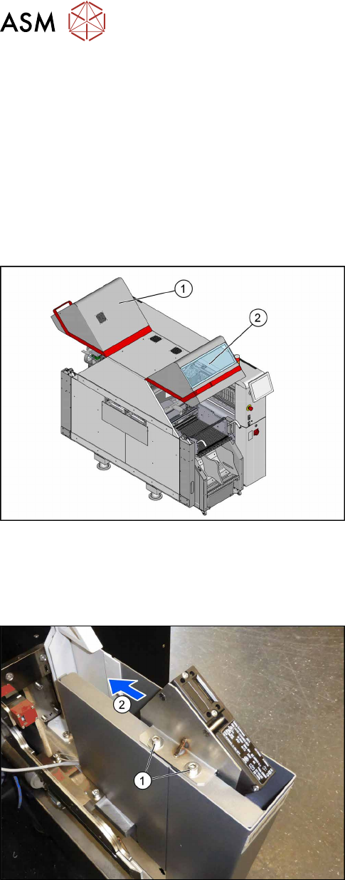
Fig.14: Cover.
1. Cover location 1
2. Cover location 2
Removal
► Switch off the machine, disconnect it from the power supply and secure it to prevent
unauthorized reactivation. Observe the instructions in section 1.2 "Preparatory Work..." [}15].
Fig.15: Screws at the cover switch
► Remove the two screws(1) fastening the cover
switch.
► Move the cover switch(2) towards the middle of
the machine, so it cannot be damaged by an un-
adjusted cover.
2 Basic Machine
2.4 Replacing the Cover
Service Manual SIPLACE TX Series 06/2017 29
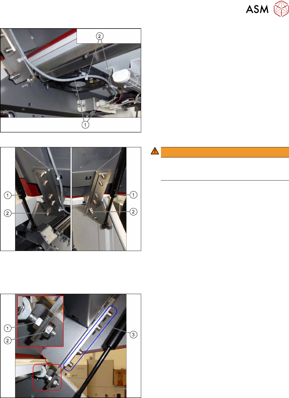
Fig.16: Cover fan
► Unplug the cover fan cable(1).
► Remove the cable ties(2).
Fig.17: Removing the cover
WARNING!
Hold the cover
Make sure a second person is holding the cover
when removing it in the following steps.
.
► Remove the two gas pressure shock ab-
sorbers(1) (see 2.2 "Replacing the Gas Pressure
Shock Absorber on the Cover" [}24]).
► Remove the two nuts(2)holding the machine
cover.
► Remove the cover.
Installation
► Follow the removal instructions in reverse order for installation. Also observe the following in-
structions:
Fig.18: Installation
Installation instructions:
► Set the protective machine cover.
Use the nuts(1) and(2) for adjusting the height.
Use the screws(3) for setting the left/right side
and the depth.
► Set the actuator for the cover (see below).