00198150-02_SM_TX_en.pdf - 第97页
6 Gantries 6.3 Trailing Cable and Printed Circuit Boards Service Manual SIPLACE TX Series 06/2017 97 Fig.108: Trailing cable interface Trailing cable interface [03115810-xx] 1. Six fastening screws NOTICE! Inverse lay…
6 Gantries
6.3 Trailing Cable and Printed Circuit Boards
96 Service Manual SIPLACE TX Series 06/2017
6.3 Trailing Cable and Printed Circuit Boards
6.3.1 Gantries – Trailing Cables and Boards – Overview
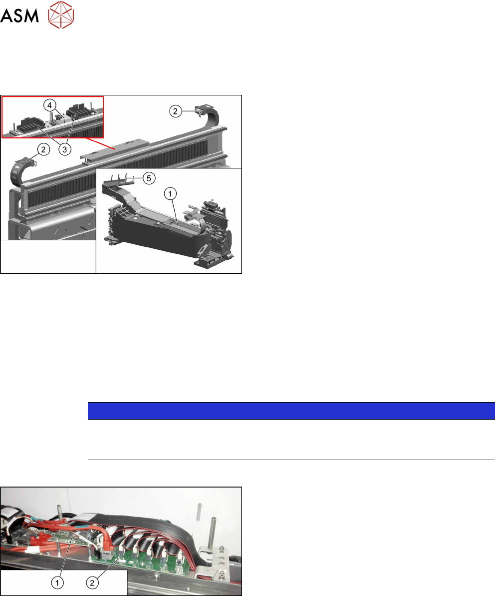
Fig.106: Trailing cables and boards
1. X axis trailing cable
6.3.6.1 "Replacing the X Axis Trailing
Cable" [}103]
2. Y axis trailing cable
6.3.6.2 "Replacing the Y Axis Trailing
Cable" [}108]
3. Trailing cable interface
6.3.2 "Replacing the Trailing Cable Inter-
face" [}96]
4. Vision base interface (VBI)
6.3.3 "Replacing the Vision Base Interface (VBI)
[03115474-xx]" [}98]
5. Gantry interface (mounting position)
6.3.4 "Replacing the Gantry Interface" [}99]
●
6.3.5 "Handling the Hose Unlocking Tool
[03047090-xx]" [}102]
6.3.2 Replacing the Trailing Cable Interface
Parts, equipment and tools
●
Trailing interface 1 [03115810-xx]
●
Trailing interface 2 [03115814-xx]
NOTICE
SIPLACE TX micron machines
The functionality level of the trailing cable interface must be at least -02 for SIPLACE TX
micron machines.
Overview
Fig.107: Vision base interface and trailing cable interface
1. Vision base interface (VBI)
2. Trailing cable interface
6 Gantries
6.3 Trailing Cable and Printed Circuit Boards
Service Manual SIPLACE TX Series 06/2017 97
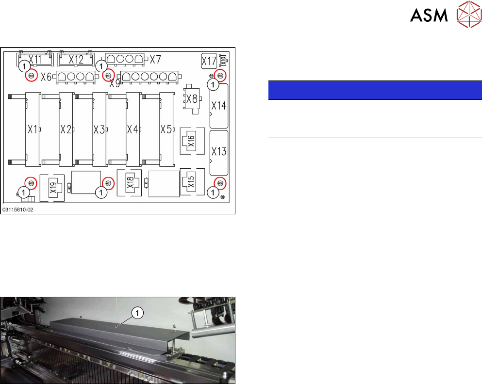
Fig.108: Trailing cable interface
Trailing cable interface [03115810-xx]
1. Six fastening screws
NOTICE!
Inverse layout
The layout of the two trailing cable interfaces is
the same, but inversely.
.
Removal
► Switch off the machine, disconnect it from the power supply and secure it to prevent
unauthorized reactivation. Observe the instructions in section 1.2 "Preparatory Work..." [}15].
Fig.109: Cover
► Remove the screws fastening the cover(1) on
the trailing cable interface and remove the cover.
► Unplug the electrical connections to the trailing cable interface. You may want to mark the
position to make clear assignment easier later on.
► Remove the six screws fastening the trailing cable interface and remove the interface from the
machine.
Installation
► Follow the removal instructions in reverse order for installation.
6 Gantries
6.3 Trailing Cable and Printed Circuit Boards
98 Service Manual SIPLACE TX Series 06/2017
6.3.3 Replacing the Vision Base Interface (VBI) [03115474-xx]
Parts, equipment and tools
●
Vision base interface [03115474-xx]
Overview
Fig.110: Vision base interface and trailing cable interface
1. Vision base interface (VBI)
2. Trailing cable interface
Removal / installation
► Removal and installation of the VBI is the same as that for the trailing cable interface. For
more information, read section Replacing the Trailing Cable Interface.
► Checking the embedded software and performing a download if needed (see LINK).
eSW Download (SW 70x) [}130]
See also
2 Vision Base Interface [03115474-xx] [}98]
2 eSW Download (SW 70x) [}130]
2 eSW Download (SW 70x) [}130]
6.3.3.1 Vision Base Interface [03115474-xx]
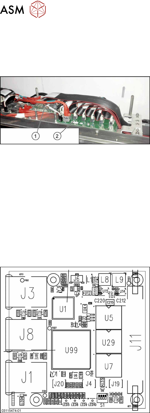
Fig.111: Vision base interface
The Vision base interface is fitted next to the trailing
cable interface.
J1: Not used
J3: BoxPC
J4: Not used
J6: Power supply
J8: Stationary Camera
J11: Trailing cable (head)
J19: Not used
J20: Not used