00198150-02_SM_TX_en.pdf - 第150页
7 Conveyor 7.3 Conveyor Drive 150 Service Manual SIPLACE TX Series 06/2017 Removal ► Use the software or manually move the conveyor rail into a position which allows you best ac- cess. – To move the conveyor rail manuall…
7 Conveyor
7.3 Conveyor Drive
Service Manual SIPLACE TX Series 06/2017 149
7.3.2 Replacing the Toothed Belts (Conveyor Drives) [03121566-xx]
Parts, equipment and tools
●
Belt tension measuring device [00326015‑xx]
Select the required toothed belt:
1. Toothed belt Synchroflex 5+-0.1 AT3/201
[03121566‑xx]
210 +/- 20 Hz
2. Toothed belt Brecoflex 5+-0.1 AT3/1701
[03121584‑xx]
Width adjustment for conveyor in lane2 (longer,
outside)
21 +/- 2 Hz
3. Toothed belt Brecoflex 5+-0.1 AT3/1509
[03121586‑xx]
Width adjustment for conveyor in lane1 (shorter,
inside)
25 +/- 2 Hz
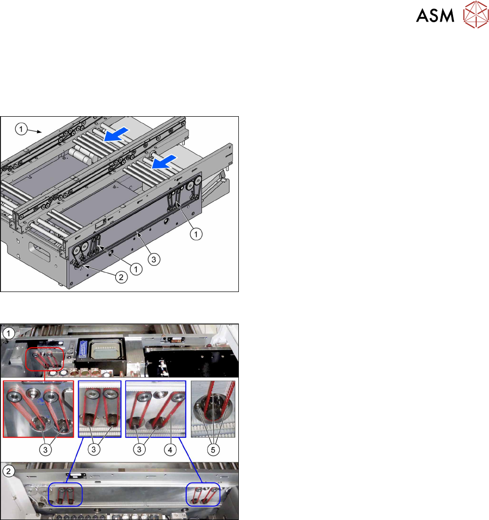
Overview
Fig.202: Conveyor drives and toothed belts
1. Conveyor drives in lane 1 (location 1)
2. Conveyor drives in lane 2 (location 2)
3. Six conveyor drives
4. Toothed belt for conveyor drives
5. Three screws fastening the conveyor drives
7 Conveyor
7.3 Conveyor Drive
150 Service Manual SIPLACE TX Series 06/2017
Removal
► Use the software or manually move the conveyor rail into a position which allows you best ac-
cess.
– To move the conveyor rail manually, pull the toothed belt of the width adjustment unit.
► Switch off the machine, disconnect it from the power supply and secure it to prevent
unauthorized reactivation. Observe the instructions in section 1.2 "Preparatory Work..." [}15].
► Move all gantries out of the transport area as far as possible at one side of the machine.
► The fastening screws of the conveyor drives are on the outer side of the conveyor. You may
have to move out the COTi to get access to these screws. In this case follow the instructions
to move out the COTi.
Replacing the COTi Central Unit and Lifting Mechanics [}235]
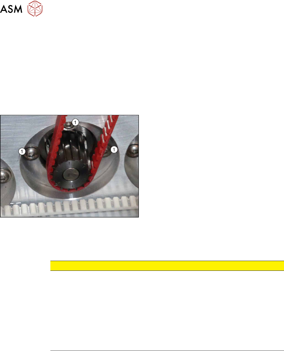
Fig.203: Fastening screws
► Loosen the three screws (1) fastening the con-
veyor drive.
► Carefully unthread the toothed belt from the mo-
tor.
Installation
► Follow the removal instructions in reverse order for installation. Also observe the following in-
structions:
CAUTION
Installation instructions
► Make sure that the toothed belt is not folded or otherwise damaged.
► Make sure that the toothed belt is accurately positioned in the guidance on the motor
shaft.
► Carefully thread in the toothed belt. To do this, carefully lift the toothed belt a little (e.g.
with the shorter end of an Allen key).
► Tighten the three screws fastening the conveyor drive hand-tight. Set the tension of
the toothed belt correctly in same time at 210+-20Hz.
► The installation position for some drivers may need to be adjusted to suit the belt ten-
sion of the width adjustment and synchroflex (red).
See also
2 Replacing the COTi Central Unit and Lifting Mechanics [}235]
2 Setting the Tension of the Conveyor Toothed Belt [}159]
2 Replacing the COTi Central Unit and Lifting Mechanics [}235]
7 Conveyor
7.3 Conveyor Drive
Service Manual SIPLACE TX Series 06/2017 151
7.3.3 Replacing the Cables (Conveyor Drive)
Parts, equipment and tools
●
Select the relevant cable:
– Cable PCB sensor LB12.A1 [03113837‑xx]
– Cable PCB sensor LB14.A1 [03113840‑xx]
– Sensor cable belt motor output lane 1 [03113852-xx]
– Motor cable width adjustment lane 1 [03113854‑xx]
– Motor cable belt motor output lane 1 [03113870‑xx]
– Motor cable width adjustment lane 1 [03113871‑xx]
– Cable can-bus internal conveyor controller SX2 [03088836‑xx]
– Cable PCB centering laser LLBt2 panel-C [03113847‑xx]
– Cable PCB centering laser LLBr2 panel-D [03113848‑xx]
●
Loctite 241 [02101037‑xx]
Removal
CAUTION
Do not loosen the wrong screws
Make sure that you do not loosen any other screws except those ones explicitly mentioned.
Loosening other screws could lead to irreparable misalignment or damage to the conveyor.
► Use the software or manually move the conveyor rail into a position which allows you best ac-
cess.
– To move the conveyor rail manually, pull the toothed belt of the width adjustment unit.
► Switch off the machine, disconnect it from the power supply and secure it to prevent
unauthorized reactivation. Observe the instructions in section 1.2 "Preparatory Work..." [}15].
► Move all gantries out of the transport area as far as possible at one side of the machine.
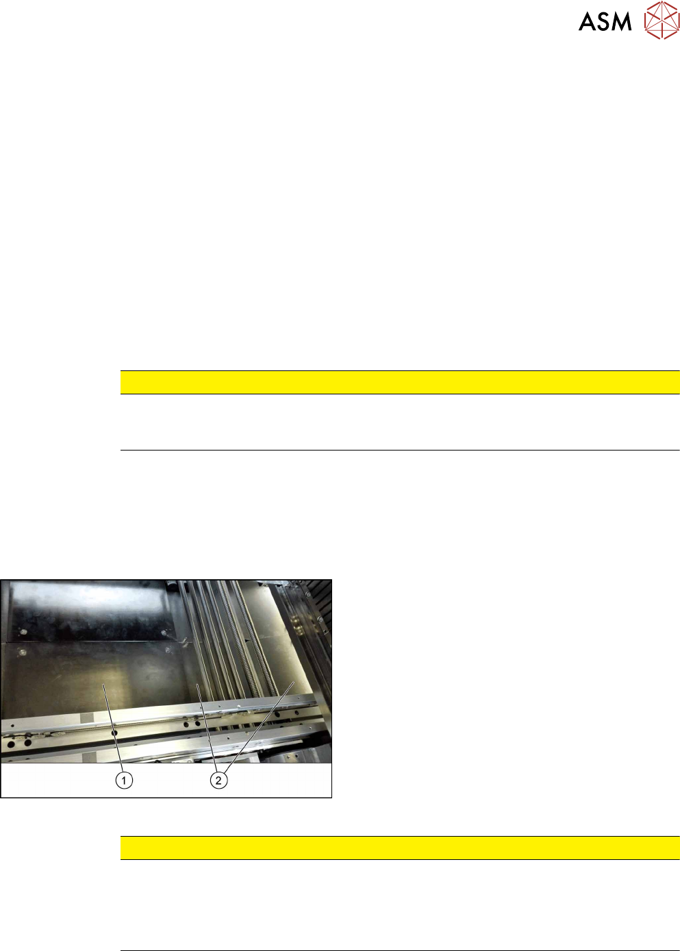
Fig.204: Table plate and covers
► Remove the four screws fastening the lifting table
plate(1) (see also 7.2.1 "Replacing the Lifting
Table Plate [03114873-xx]" [}136]).
► Remove the spacer bolts fastening the covers(2)
(two screws each cover) and remove the covers.
CAUTION
Make a note of the order in which the cables are run!
The room in the conveyor side walls is limited. The cables may therefore not be crossed
over.
Make a note of the order in which the cables are run in the conveyor side wall, so that you
can run them neatly and correctly again later on.