00198150-02_SM_TX_en.pdf - 第94页
6 Gantries 6.2 X and Y Axis 94 Service Manual SIPLACE TX Series 06/2017 Installation ► Follow the removal instructions in reverse order for installation. Also observe the following in- structions: Fig.104: Setting the h…
6 Gantries
6.2 X and Y Axis
Service Manual SIPLACE TX Series 06/2017 93
6.2.9 Replacing Attachment Head Suspension [03124850-xx]
Parts, equipment and tools
●
Attachment complete head suspension [03124850‑xx]
Removal
► Switch off the machine, disconnect it from the power supply and secure it to prevent
unauthorized reactivation. Observe the instructions in section 1.2 "Preparatory Work..." [}15].
► Remove the placement head.
Replacing the SIPLACE C&P20 P/M2 Head [}202]
Replacing the SIPLACE CPP/M Head [}206]
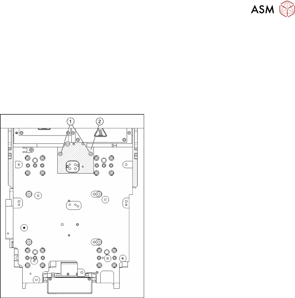
Fig.103: Head suspension
► Remove the two screws(1) fastening the head
suspension(2).
► Remove the head suspension carefully.
6 Gantries
6.2 X and Y Axis
94 Service Manual SIPLACE TX Series 06/2017
Installation
► Follow the removal instructions in reverse order for installation. Also observe the following in-
structions:
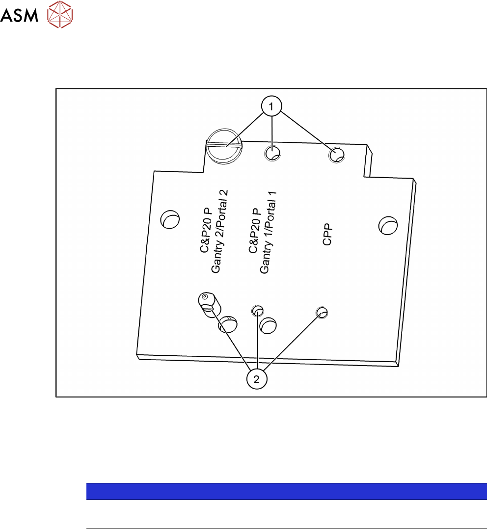
Fig.104: Setting the head suspension
► Position the screws(1) and (2) in relation to the head and the gantry.
See also
2 Replacing the SIPLACE C&P20 P/M2 Head [}202]
2 Replacing the SIPLACE CPP/M Head [}206]
6.2.10 Installation Check for X Motor Plate
NOTICE
SIPLACE Service
This task may only be performed by SIPLACE service technicians.
6 Gantries
6.2 X and Y Axis
Service Manual SIPLACE TX Series 06/2017 95
Installation Check
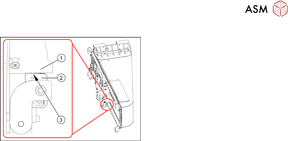
Fig.105: X drive (using example of X-Series)
1. X motor plate
2. Guide trolley
3. 0.5mm gap between motor plate and top edge of
linear guide
► When installing the X motor plate, place a feeler
gauge(3) of 0.5mm between the X motor plate
and guide trolley.
► If the distance is too low, remove the X drive and
fit it again.