00198150-02_SM_TX_en.pdf - 第191页
7 Conveyor 7.9 Checking Parallelism of Conveyor Rails Service Manual SIPLACE TX Series 06/2017 191 7.9 Checking Parallelism of Conveyor Rails Fig.256: Select operator level ► Click the button to enter the Settings menu.…
7 Conveyor
7.8 Setting the Fixed Conveyor Rail
190 Service Manual SIPLACE TX Series 06/2017
7.8.1 Conveyor Rails - Settings
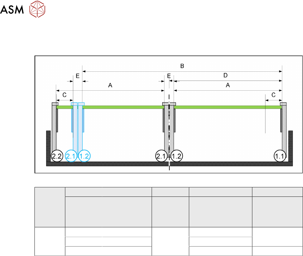
The following diagram shows a conveyor with the fixed conveyor side on the right. The same set-
tings apply to conveyors with the fixed side on the left.
Fig.255: View of a conveyor with a fixed side on the right (SIPLACE X-Series S as example)
SIPLACE
TX-
Series
A B C D E
Maximum
PCB width
Dual as single
conveyor
(flex)
Minimum
PCB width
Position of fixed
conveyor side
(from the
conveyor center)
Minimum
side wall dis-
tance
Side wall 1.2/2.1
Dual con-
veyor
236 433 45 mm 231 45 mm
250 450 268
260 460 281 35 mm
7 Conveyor
7.9 Checking Parallelism of Conveyor Rails
Service Manual SIPLACE TX Series 06/2017 191
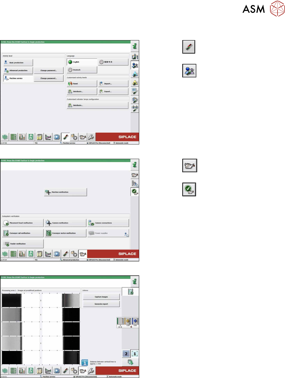
7.9 Checking Parallelism of Conveyor Rails
Fig.256: Select operator level
► Click the
button to enter the Settings
menu.
► Click the
button to open the Check and set
user settings menu.
► Switch to operator level Machine service or bet-
ter.
Fig.257: Maintenance menu
► Click the
button to enter the maintenance
menu.
► Click the
button.
► Click the Conveyor rail verification button.
Fig.258: Conveyor rail verification
► Click the Capture images button to run check.
► Click the Generate report button to view details.
7 Conveyor
7.10 Teaching the PCB Sensors (SW70x)
192 Service Manual SIPLACE TX Series 06/2017
7.10 Teaching the PCB Sensors (SW70x)
Whenever you manually loosen the conveyor sides, you also need to reteach the light barrier
sensors. This is required because the light intensity depends on the conveyor width. Without teach-
ing, the conveyor will show boards which are not present, preventing the conveyor from being ref-
erenced.
Teaching is performed automatically during operation.
Procedure
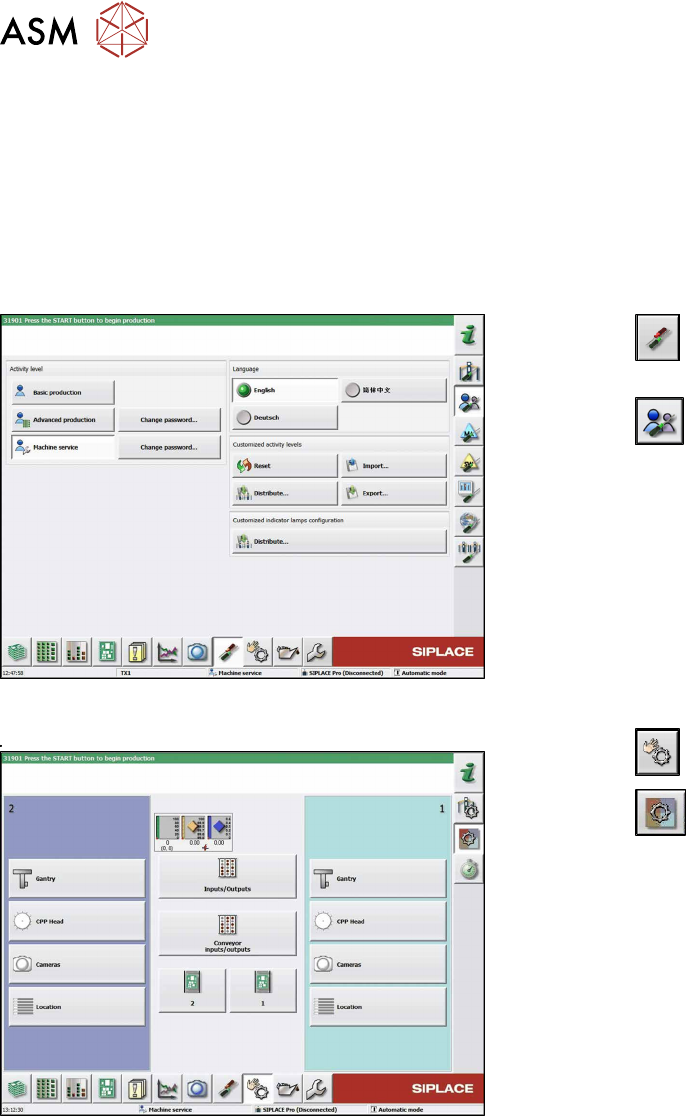
Fig.259: Select operator level
► Click the
button to enter the Settings
menu.
► Click the
button to open the Check and set
user settings menu.
► Switch to operator level Machine service or bet-
ter.
Fig.260: Checking sensors and functions
► Click the
button.
► Click the
button.
► Click on the Conveyor inputs/outputsbutton.