00198150-02_SM_TX_en.pdf - 第195页
7 Conveyor 7.11 Replacing the Fiducial Rail Service Manual SIPLACE TX Series 06/2017 195 1. Two screws fastening the fiducial rail - right side 2. Holder and fiducial rail 3. Right holder for fiducial rail ► Remove the t…
7 Conveyor
7.11 Replacing the Fiducial Rail
194 Service Manual SIPLACE TX Series 06/2017
7.11 Replacing the Fiducial Rail
Parts, equipment and tools
●
Holder with fiducial rail assembly, location 1, with calibration component pocket
[03151908Sxx]
●
Holder with fiducial rail assembly, location 2 [03147052Sxx]
Overview
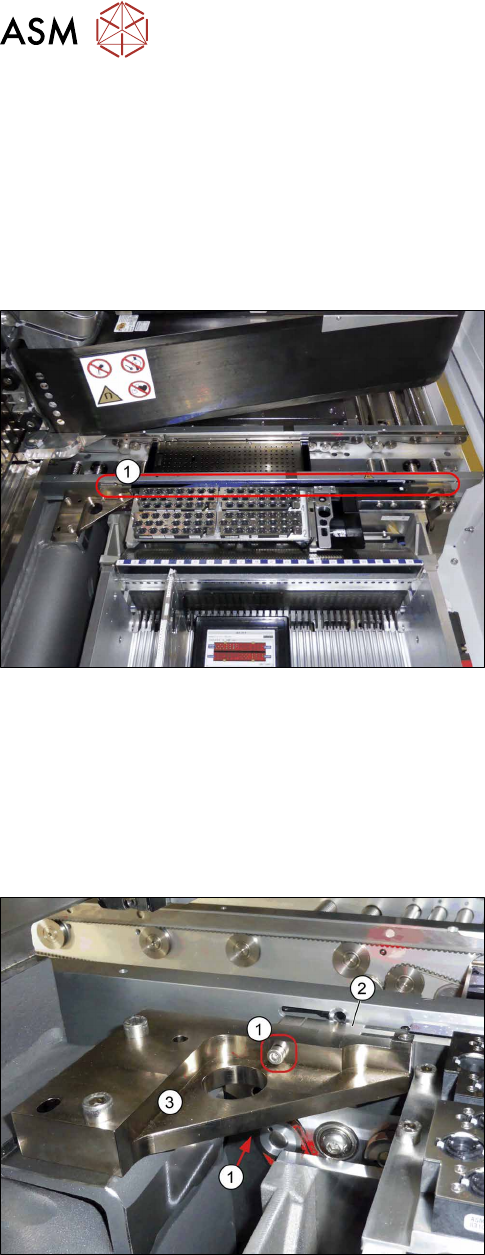
Fig.263: Holder with fiducial rail (example of location 1 shown)
1. Holder and fiducial rail
The fiducial rail is fixed to the holder (adhesive) and
may not be separated from it.
Removal
► Use the software or manually move the conveyor rail into a position which allows you best ac-
cess.
– To move the conveyor rail manually, pull the toothed belt of the width adjustment unit.
► Switch off the machine, disconnect it from the power supply and secure it to prevent
unauthorized reactivation. Observe the instructions in section 1.2 "Preparatory Work..." [}15].
1. Two screws fastening the fiducial rail - left side
2. Holder and fiducial rail
3. Left holder for fiducial rail
► Remove the two left screws fastening the fiducial
rail.
7 Conveyor
7.11 Replacing the Fiducial Rail
Service Manual SIPLACE TX Series 06/2017 195
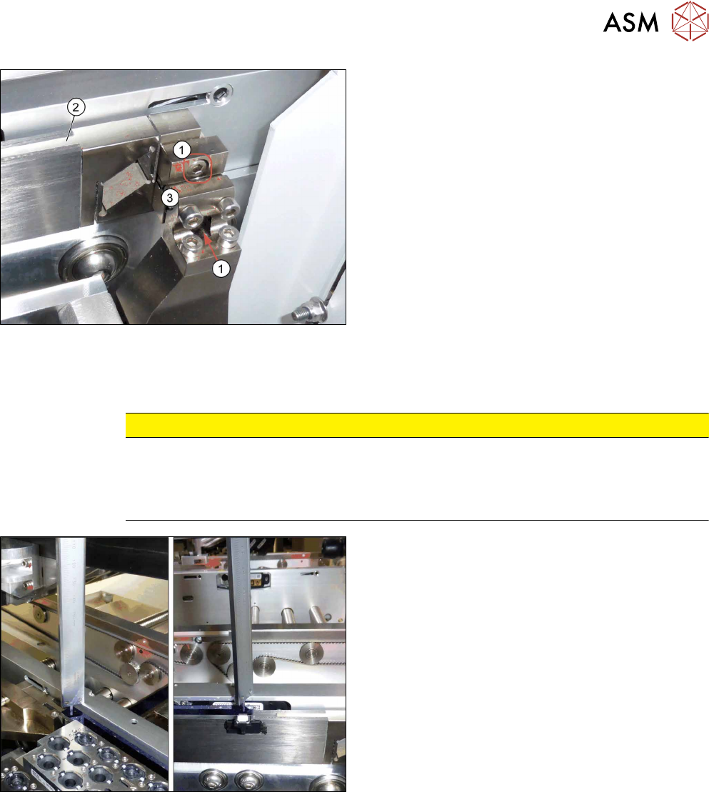
1. Two screws fastening the fiducial rail - right side
2. Holder and fiducial rail
3. Right holder for fiducial rail
► Remove the two right screws fastening the fidu-
cial rail.
Hold the fiducial rail firmly while doing this.
► Carefully take the fiducial rail up and out.
Installation
► Follow the removal instructions in reverse order for installation. Also observe the following in-
structions:
CAUTION
Installation instructions
► Make sure that you do not scratch the fiducial rail.
► Check the distance from the fiducial rail to the upper edge of the conveyor side wall
(see below).
► Check the distance from the blue fiducial rail to
the upper edge of the conveyor side wall. The
distance must be 5+/‑0.1mm.

7 Conveyor
7.12 Vacuum Tooling
196 Service Manual SIPLACE TX Series 06/2017
7.12 Vacuum Tooling
Spare parts
The following parts can be replaced for vacuum tooling:
●
Basic pack vacuum tooling TX [00588121‑xx]
●
Vacuum suction nozzle, nominal width 2 mm [03136878‑xx]
●
Maintenance unit vacuum tooling TX [03136432‑xx]
●
Valve unit assembly [03138689‑xx]
●
Cable: vacuum tooling [03139108‑xx]
●
Cable: vacuum tooling sensor [03139109‑xx]
●
Vacuum switch VSI V D M8-4 [03118829‑xx]
●
Cable: PCB sensor vacuum tooling 1 [03149630‑xx]
●
Cable: PCB sensor vacuum tooling 2 [03149631‑xx]
Equipment and tools
●
Assembly instructions "Basic pack vacuum tooling SIPLACE TX‑Series" [DE
+EN:00198328‑xx]
Removal / Installation
► For more information about replacing spare parts, please read the assembly instructions.