00198150-02_SM_TX_en.pdf - 第68页
4 Electrical System and Control 4.4 Replacing the GigE Ethernet Adapter 68 Service Manual SIPLACE TX Series 06/2017 4.4 Replacing the GigE Ethernet Adapter Parts, equipment and tools ● GigE-Ethernet-Adapter PCI-E I350 T2…
4 Electrical System and Control
4.3 Replacing the RAM in the BoxPC
Service Manual SIPLACE TX Series 06/2017 67
4.3 Replacing the RAM in the BoxPC
Parts, equipment and tools
NOTICE
Memory extension
The Windows 7/8 operating system requires 2GB of RAM.
PC type RAM module
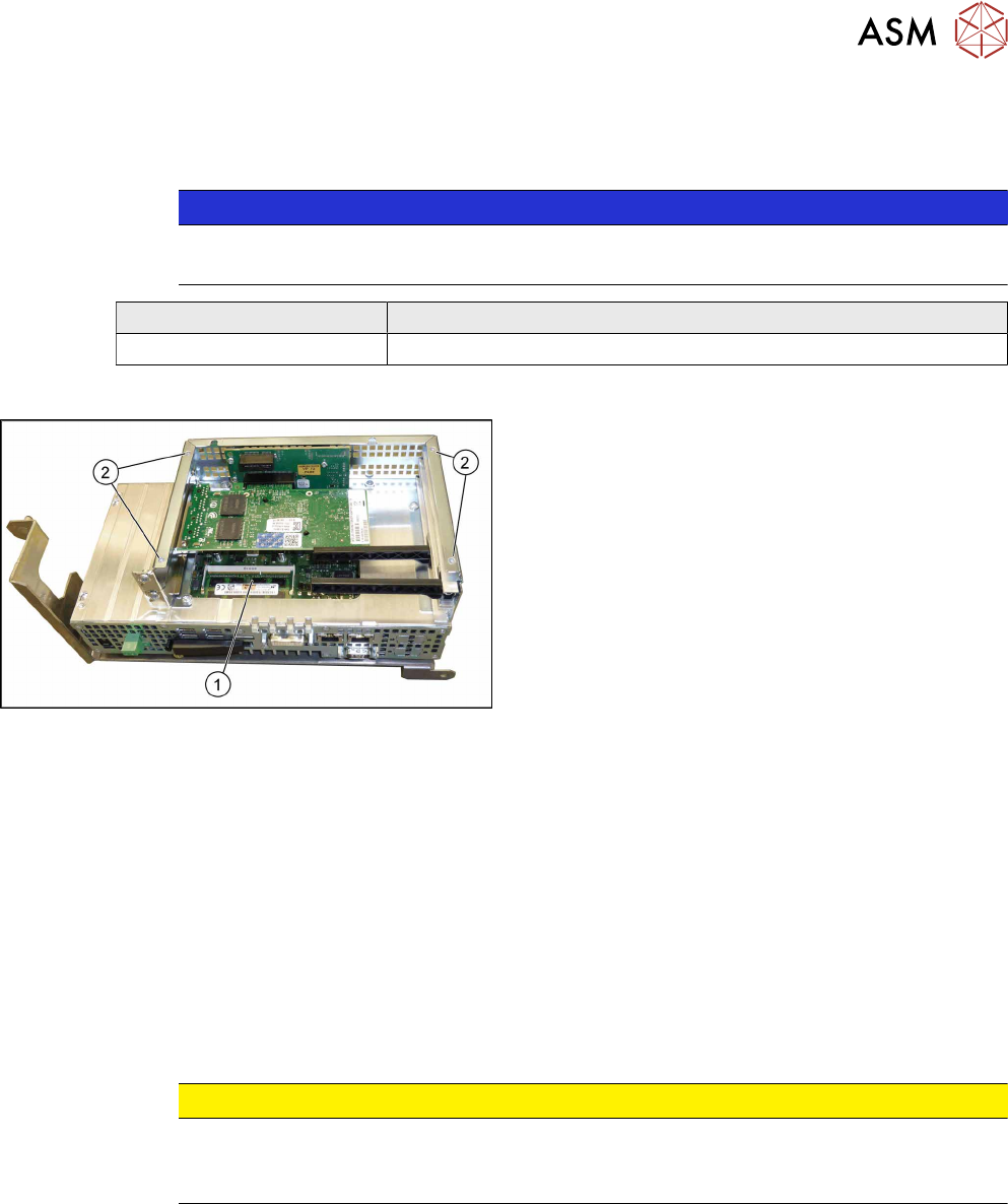
BoxPC 427D [03114177Sxx] 4 GB DDR 1333Mhz PC3-10600 SO-DIMM
Overview
Fig.72: BoxPC 427D
1. Memory extension
2. Four fastening screws for the cover
Removal
► Switch off the machine, disconnect it from the power supply and secure it to prevent
unauthorized reactivation. Observe the instructions in section 1.2 "Preparatory Work..." [}15].
► Dismantle and remove the BoxPC from the machine.
Replacing the Control Computer BoxPC [}64]
► Remove the screws fastening the cover of the BoxPC and open the cover.
► Open the locks on both sides of the memory extension and remove the memory extension.
Installation
► Follow the removal instructions in reverse order for installation. Also observe the following in-
structions:
CAUTION
Installation instructions
► Make sure that you insert the memory extension the right way round. The new
memory extension must audibly engage into its slot.
See also
2 Replacing the Control Computer BoxPC [}64]
4 Electrical System and Control
4.4 Replacing the GigE Ethernet Adapter
68 Service Manual SIPLACE TX Series 06/2017
4.4 Replacing the GigE Ethernet Adapter
Parts, equipment and tools
●
GigE-Ethernet-Adapter PCI-E I350 T2 V2 BLK [03115569‑xx]
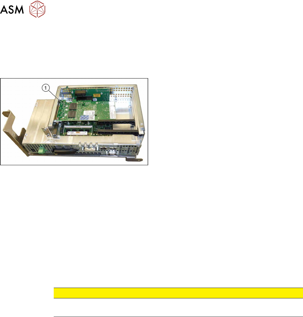
Overview
Fig.73: GigE Ethernet adapter in the BoxPC 427D
1. GigE ethernet adapter
Removal
The ethernet adapter is fitted in the BoxPC.
► Switch off the machine, disconnect it from the power supply and secure it to prevent
unauthorized reactivation. Observe the instructions in section 1.2 "Preparatory Work..." [}15].
► Dismantle and remove the BoxPC from the machine.
Replacing the Control Computer BoxPC [}64]
► Remove the screws fastening the cover of the BoxPC and open the cover.
► Remove the screw fastening the Ethernet adapter and remove the Ethernet adapter.
Installation
► Follow the removal instructions in reverse order for installation. Also observe the following in-
structions:
CAUTION
Installation Instructions
► Make sure that the plug-in card is correctly fitted into its slot.
See also
2 Replacing the Control Computer BoxPC [}64]
4 Electrical System and Control
4.5 Replacing the Monitor [03115169-xx]
Service Manual SIPLACE TX Series 06/2017 69
4.5 Replacing the Monitor [03115169-xx]
Parts, equipment and tools
●
Monitor DV1224-007 12.1 inch [03115169-xx]
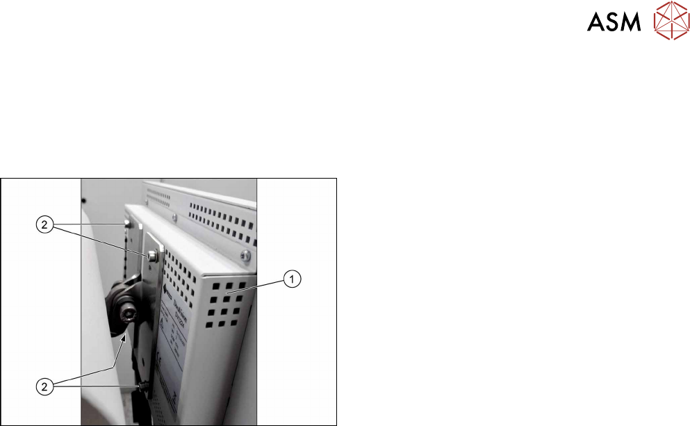
Overview
Fig.74: Monitor on machine
1. Monitor
2. Four fastening screws
Removal
► Switch off the machine, disconnect it from the power supply and secure it to prevent
unauthorized reactivation. Observe the instructions in section 1.2 "Preparatory Work..." [}15].
► Unplug all connections to the monitor. You might like to mark their positions to make clear as-
signment easier later on.
► Remove the four screws fastening the monitor to its bracket. You will need the monitor
bracket when fitting the new monitor.
Installation
► Follow the removal instructions in reverse order for installation.