00198150-02_SM_TX_en.pdf - 第285页
12 SIPLACE TX-Series Component Trolley 12.7 Replacing the Feeder Centering [03028910-xx] Service Manual SIPLACE TX Series 06/2017 285 12.6.1 Setting the Actuator on the Component Trolley Fig.402: Setting the actuator ► …
12 SIPLACE TX-Series Component Trolley
12.6 Replacing the Actuator/Protective Bracket
284 Service Manual SIPLACE TX Series 06/2017
12.6 Replacing the Actuator/Protective Bracket
Parts, equipment and tools
●
Torx screwdriver ESD 1.0-5.0 Nm [03078400-xx]
●
Bit holder for TorqueVario screwdriver [03078706-xx]
●
Bit 1/4, TX20 with hole drilled [03148413‑xx]
●
Safety switch D4DS-K3 [03107666-xx]
●
Protective bracket: holder and protector for actuator [03126075-xx]
Overview
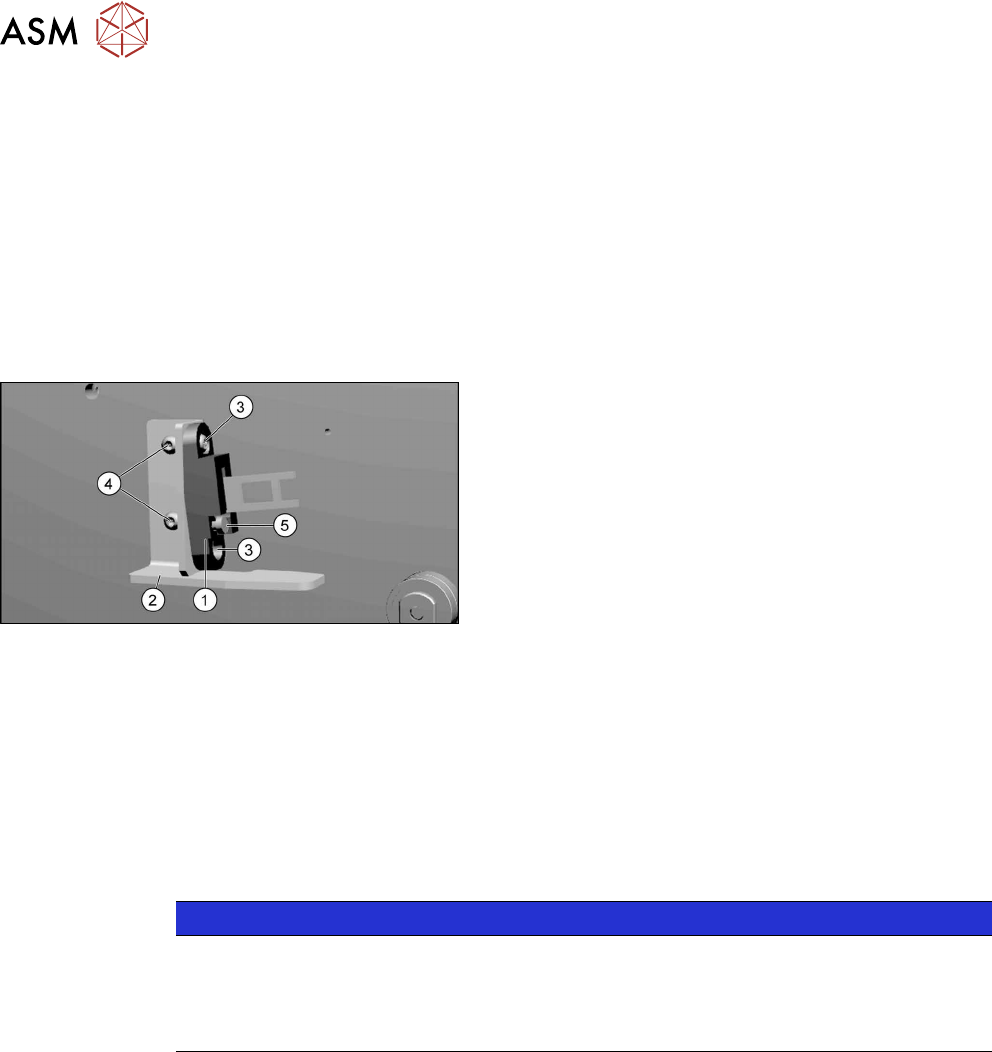
Fig.401: Actuator and protective bracket on component trol-
ley
1. actuator
2. Protective bracket
3. Two fastening screws actuator
4. Two fastening screws protective bracket
5. Adjustment screw for actuator angle
Removal
► Remove the fastening screws of the actuator/protective bracket.
► Remove the actuator/protective bracket.
Installation
► Follow the removal instructions in reverse order for further installation. Also observe the fol-
lowing instructions:
NOTICE
Installation instructions
► Tighten the fastening screws for the actuator on the protective bracket with a max-
imum torque of 2.0Nm.
► Set the actuator (see below).
See also
2 Setting the Actuator on the Component Trolley [}285]
12 SIPLACE TX-Series Component Trolley
12.7 Replacing the Feeder Centering [03028910-xx]
Service Manual SIPLACE TX Series 06/2017 285
12.6.1 Setting the Actuator on the Component Trolley
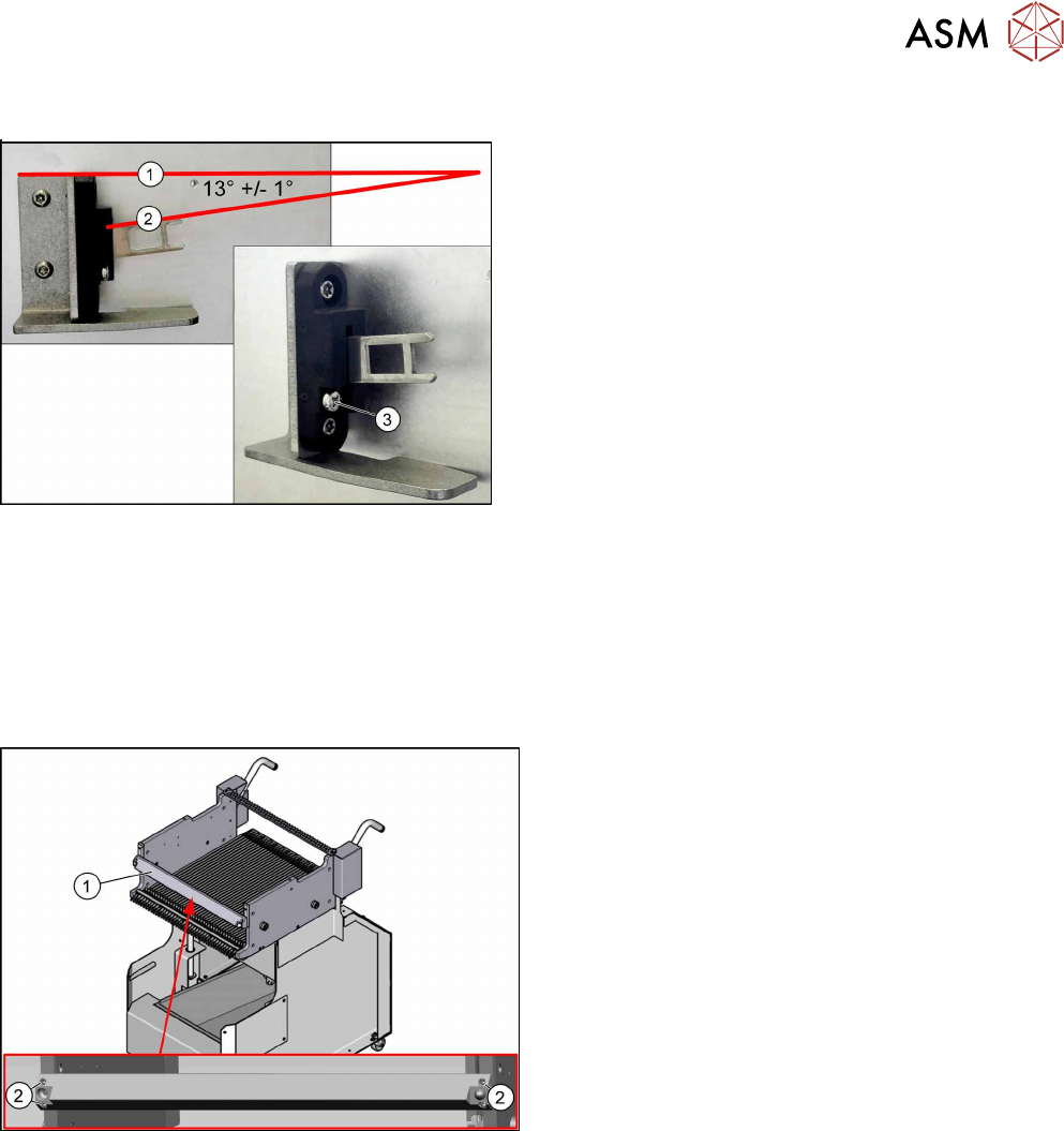
Fig.402: Setting the actuator
► Set the actuator with the help of the adjustment
screw (3).
Between the upper edge(1) of the table and the ac-
tuator(2) you need to set an angle of 13°+/‑1°.
The actuator must be able to slide into the safety
switch without rubbing against the plastic.
12.7 Replacing the Feeder Centering [03028910-xx]
Parts, equipment and tools
●
Feeder centering X-Series [03028910‑xx]
Overview
Fig.403: Feeder centering on component trolley
1. Feeder centering
2. Four fastening screws for the feeder centering
Removal
► Remove the four screws fastening the feeder centering.
► Remove the feeder centering.
Installation
► Follow the removal instructions in reverse order for installation.

12 SIPLACE TX-Series Component Trolley
12.7 Replacing the Feeder Centering [03028910-xx]
286 Service Manual SIPLACE TX Series 06/2017