00198150-02_SM_TX_en.pdf - 第206页
8 Placement Heads and Stationary Cameras 8.3 Replacing the SIPLACE CPP/M Head 206 Service Manual SIPLACE TX Series 06/2017 8.3 Replacing the SIPLACE CPP/M Head NOTICE Vacuum test ► If required, perform a vacuum test befo…
8 Placement Heads and Stationary Cameras
8.2 Replacing the SIPLACE C&P20 P/M2 Head
Service Manual SIPLACE TX Series 06/2017 205
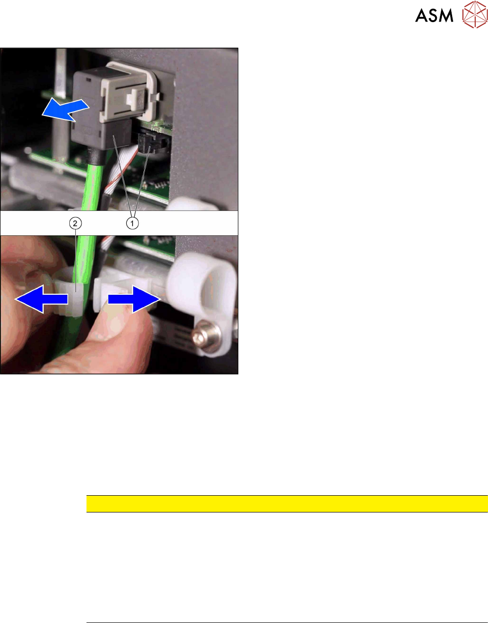
Fig.279: Connectors to VHI
► Remove the two connectors(1) to the VHI board.
► Open the cable holder(2) and unthread the
cable.
► Unscrew all four M4 fastening screws with a long Torx key.
► Carefully lift the placement head out of the locating pins on the head plate and from the hook.
► Placing the head into the head transport box
Installation
► Follow the removal instructions in reverse order for installation. Also observe the following in-
structions:
CAUTION
Installation instructions
► If you replace the placement head without the component camera, you will need to fit
the old camera into the new head. In this case a full calibration is necessary. Read the
service manual for your placement head for more information.
► For compressed air mode, the placement head must be converted using the "Hold-cir-
cuit assembly/C&P20" [03005123Sxx].
► Make sure that the assembly position on the head plate is correct.
► Tighten the four head fastening screws (M4) with a torque of 2.7 Nm.
8 Placement Heads and Stationary Cameras
8.3 Replacing the SIPLACE CPP/M Head
206 Service Manual SIPLACE TX Series 06/2017
8.3 Replacing the SIPLACE CPP/M Head
NOTICE
Vacuum test
► If required, perform a vacuum test before removing the placement head.
Read the "Service manual Vacuum test at C&P placement head" [DE+EN:
00196101‑xx] for this.
NOTICE
Fast Head Exchange (FHE)
► Observe the instructions in section 8.1 "Fast Head Exchange" [}197] when exchan-
ging a head.
Parts, equipment and tools
●
SIPLACE CPP placement head [03053528Sxx] (without camera)
●
SIPLACE CPP M placement head [03153719Sxx] (without camera)
●
Torx screwdriver ESD 1.0-5.0 Nm [03078400-xx]
●
Extension/straight TX20 [03073256-xx]
●
Bit holder for TorqueVario screwdriver [03078706-xx]
●
Component sensor protective cap [03080984-xx]
●
Calibration tool version 3 [03010565-xx]
●
Calibration tool version SST23 [03034148-xx]
For additional work to the placement head:
●
Head mount [03056231‑xx]
●
Service manual "SIPLACE CPP head" [DE:00197462‑xx] [EN:00197463‑xx]
Overview
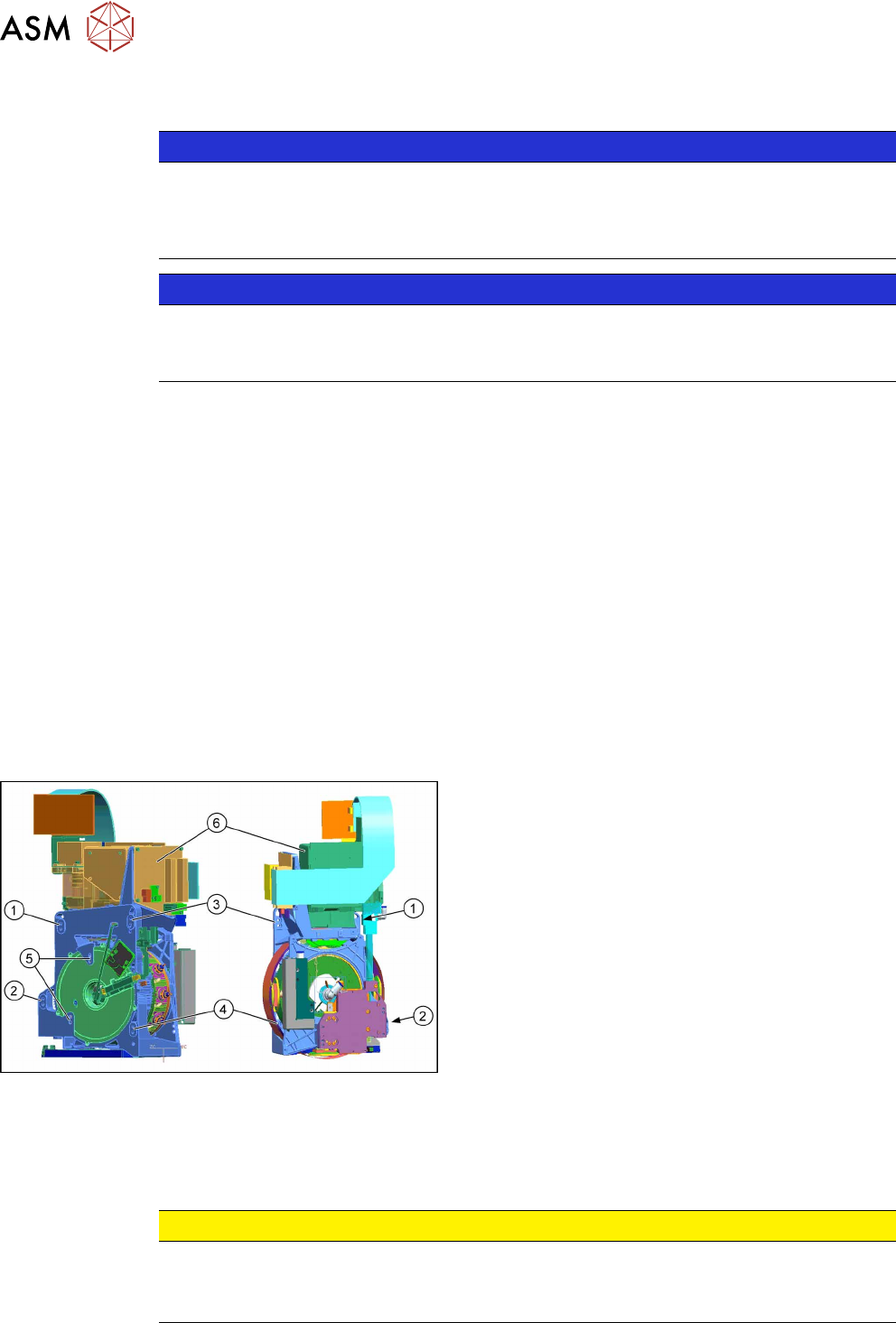
Fig.280: Overview (example of CPP head shown)
1 to 4: Fixture holes (two each, depends on installa-
tion height).
5: Dowel holes for the index pins
6: Component camera
Removal
► Switch off the machine, disconnect it from the power supply and secure it to prevent
unauthorized reactivation. Observe the instructions in section 1.2 "Preparatory Work..." [}15].
CAUTION
Take great care when dismantling the placement head!
The component sensor prisms, underneath the placement head, could be damaged.
► Never place the placement head down on the component sensor.
8 Placement Heads and Stationary Cameras
8.3 Replacing the SIPLACE CPP/M Head
Service Manual SIPLACE TX Series 06/2017 207
Fig.281: Component sensor protective cap
► Fit the protective cap onto the component sensor
for the placement head.
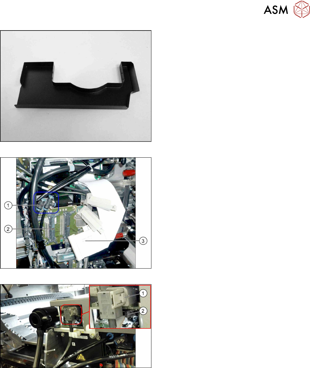
Fig.282: Connections
► Unplug the pneumatic connections(1) from the
placement head. You may want to mark the posi-
tions to make clear assignment easier later on.
► Disconnect the flat ribbon cables(3) from the in-
termediate distributor(2).
Fig.283: Cables
► Push the button(1) to unplug the cable, open the
clamps on both sides of connector to unplug the
flat ribbon cable(2).
► Remove all four screws fastening the head with a long Torx screwdriver.
► Carefully lift the head out of the locating pins on the head plate and from the hook.
► Placing the head into the head transport box