00198150-02_SM_TX_en.pdf - 第223页
8 Placement Heads and Stationary Cameras 8.7 Calibration Service Manual SIPLACE TX Series 06/2017 223 8.7.1 Calibrating the Heads and Cameras (SW70x) Fig.302: Select operator level ► Click the button to enter the Settin…

8 Placement Heads and Stationary Cameras
8.7 Calibration
222 Service Manual SIPLACE TX Series 06/2017
DIP switch S1 [03117587-xx] [03117981-01]
Switch Status Signal name Description
S1.1 OFF VCU_CODE OFF: normal operation, ON: Reset
Gantry 1 Gantry 2 Gantry 3 Gantry 4
S1.2 ON/OFF PORTAL_ID_0 OFF ON OFF ON
S1.3 ON/OFF GANTRY_ID_1 OFF OFF ON ON
S1.4 OFF SMD_LED OFF: standard LED, ON: SMD LED
S1.5 OFF CAN_H OFF: with CAN terminator
ON: without CAN terminator
S1.6 ON CAN_GROUP ON: IC camera , OFF: FC camera
8.7 Calibration
Overview
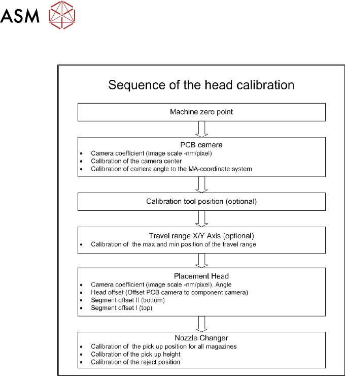
With the calibration of the component camera the following values are determined:
the relationship of "camera pixel size to resolution of machine measuring system (X,Y)", the "cam-
era center point in X and Y direction" and the "torsion angle of the CCD sensor in the camera". This
is following by determining the head offset and the segment offsets for the top and bottom.
●
Head offset: the head offset is the distance between the PCB camera and the nozzle (seg-
ment1). The target is a fixed value (X=0 and Y=‑105mm) to which an offset value (from the
head calibration) is added.
●
Segment offset top: the top segment offset involves turning the calibration tool in the compo-
nent camera in 0°, 90°, 180° and 270°. The value determined is that of the rotating center of
the nozzle tip in relation to the component camera center in the X and Y direction.
●
Segment offset bottom: the bottom segment offset involves recording and measuring the
calibration tool in the 0°, 90°, 180° and 270° positions. The value determined is that of the ro-
tating center point of the nozzle tip when the Z axis is extended in relation to the PCB camera.
Segment1 forms the reference (X=0,Y=0) to the other segments.
8 Placement Heads and Stationary Cameras
8.7 Calibration
Service Manual SIPLACE TX Series 06/2017 223
8.7.1 Calibrating the Heads and Cameras (SW70x)
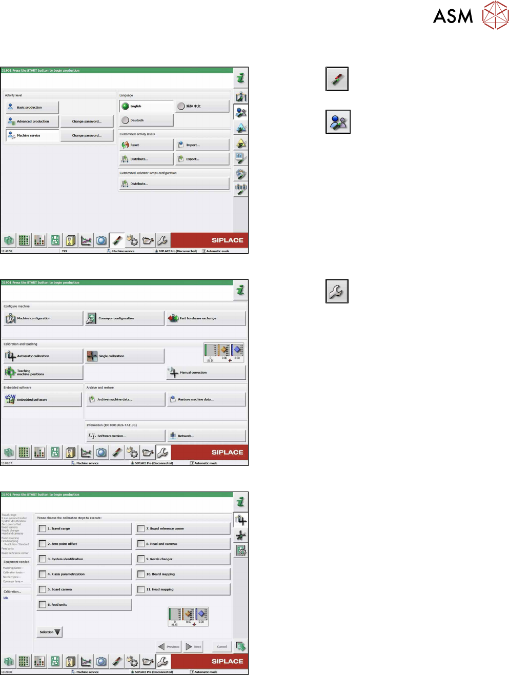
Fig.302: Select operator level
► Click the
button to enter the Settings
menu.
► Click the
button to open the Check and set
user settings menu.
► Switch to operator level Machine service or bet-
ter.
Fig.303: Service Menu
► Click the
button to enter the Service menu.
► Click the Automatic calibration button.
Fig.304: Automatic Calibration
► Select Heads and cameras.
► Click on the Continue button.
Follow the instructions on the next pages:
► On the next page, select the gantries on which
the heads to be calibrated are located and then
click on the Next button.
► The next step is to check the calibration condi-
tions (nozzle, calibration tool etc.). Follow the in-
structions provided.
After this step, calibration will begin. All required inter-
mediate steps (head height etc.) will be performed
automatically.
8 Placement Heads and Stationary Cameras
8.7 Calibration
224 Service Manual SIPLACE TX Series 06/2017
8.7.2 Calibration Procedure
Fig.305: C&P calibration procedure