00198150-02_SM_TX_en.pdf - 第259页
11 Cutter 11.7 Replacing the Articulated Joint on the Short-Stroke Cylinder [03000518-xx] Service Manual SIPLACE TX Series 06/2017 259 11.7 Replacing the Articulated Joint on the Short-Stroke Cylinder [03000518-xx] Parts…
11 Cutter
11.6 Replacing the Protective Guard [03019894-xx]
258 Service Manual SIPLACE TX Series 06/2017
11.6 Replacing the Protective Guard [03019894-xx]
Parts, equipment and tools
●
Protective guard [03019894-xx]
Overview
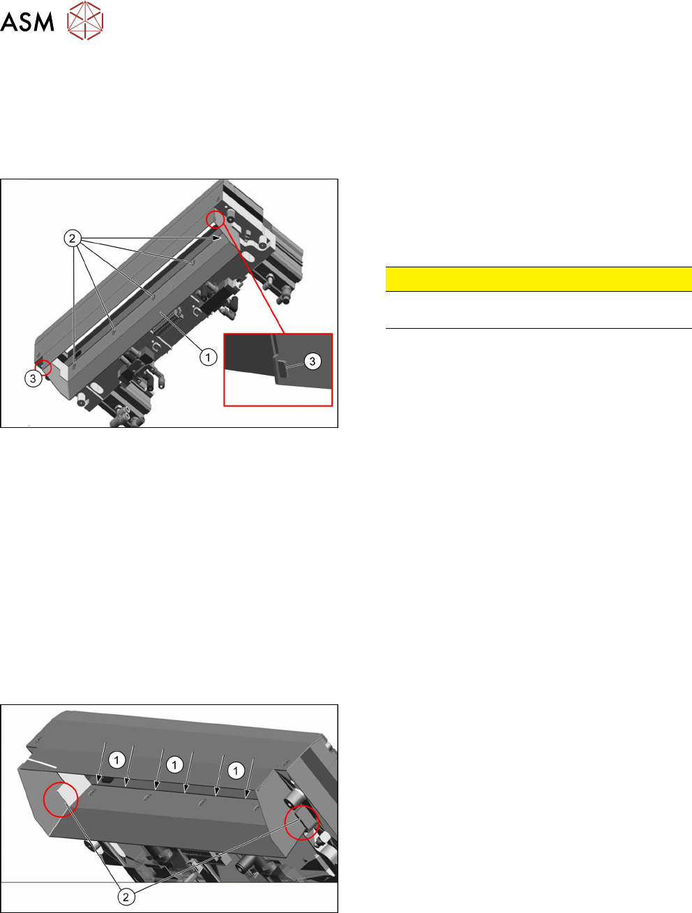
Fig.356: Protective guard on cutter
1. Protective guard [03019894-xx]
2. Five fastening screws
3. Clip connecting baffle plate and protective guard
CAUTION!
There is a risk of injuring yourself on the cutting
edge of the blades.
.
Removal
► Switch off the machine, disconnect it from the power supply and secure it to prevent
unauthorized reactivation. Observe the instructions in section 1.2 "Preparatory Work..." [}15].
► Remove the cutter from the machine.
Replacing the Cutter on the COT Insert [03066690-xx] [}252]
► Remove the five screws fastening the protective guard.
► Straighten the two clips with pliers.
► Remove the protective guard from the cutter.
Installation
► Follow the removal instructions in reverse order for installation. Also observe the following in-
structions:
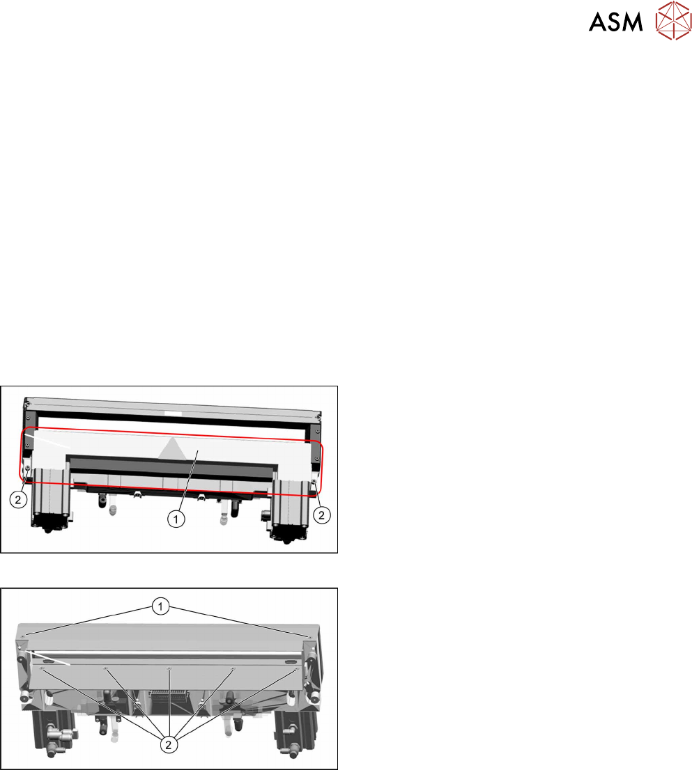
Fig.357: Fitting the protective guard
► Make sure that the five fastening screws are
completely countersunk. The screws must be
flush with the protective guard.
► Ensure that there is a gap between the cutter
blade and the edge of the baffle plate inside(1).
► If everything is correct, there should be a contact
at position(2).
See also
2 Replacing the Cutter on the COT Insert [03066690-xx] [}252]
11 Cutter
11.7 Replacing the Articulated Joint on the Short-Stroke Cylinder [03000518-xx]
Service Manual SIPLACE TX Series 06/2017 259
11.7 Replacing the Articulated Joint on the Short-Stroke
Cylinder [03000518-xx]
Parts, equipment and tools
●
Articulated joint on the short-stroke cylinder [03000518-xx]
●
2x hexagon socket fillister head screws ISO4762-M5x35-12.9, geomet. 321+VL [03057290-
xx] (screws for movable blade)
●
Torque wrench 2.5 - 25 Nm [00376625-xx]
●
Klüber BEM 34-132 lubricant grease, 1 kg tin [00374565-xx]
●
Loctite 243 [00334892‑xx]
Removing the articulated joint
► Switch off the machine, disconnect it from the power supply and secure it to prevent
unauthorized reactivation. Observe the instructions in section 1.2 "Preparatory Work..." [}15].
► Remove the cutter from the machine.
Replacing the Cutter on the COT Insert [03066690-xx] [}252]
Fig.358: Cover plate
► Remove the screws(2) fastening the top cover
plate(1) and then remove the top cover plate.
Fig.359: Baffle plate
► Remove the two screws(1) at the front side and
five screws(2) at the inner side fastening the
baffle plate.
► Remove the baffle plate unit from the cutter.
11 Cutter
11.7 Replacing the Articulated Joint on the Short-Stroke Cylinder [03000518-xx]
260 Service Manual SIPLACE TX Series 06/2017
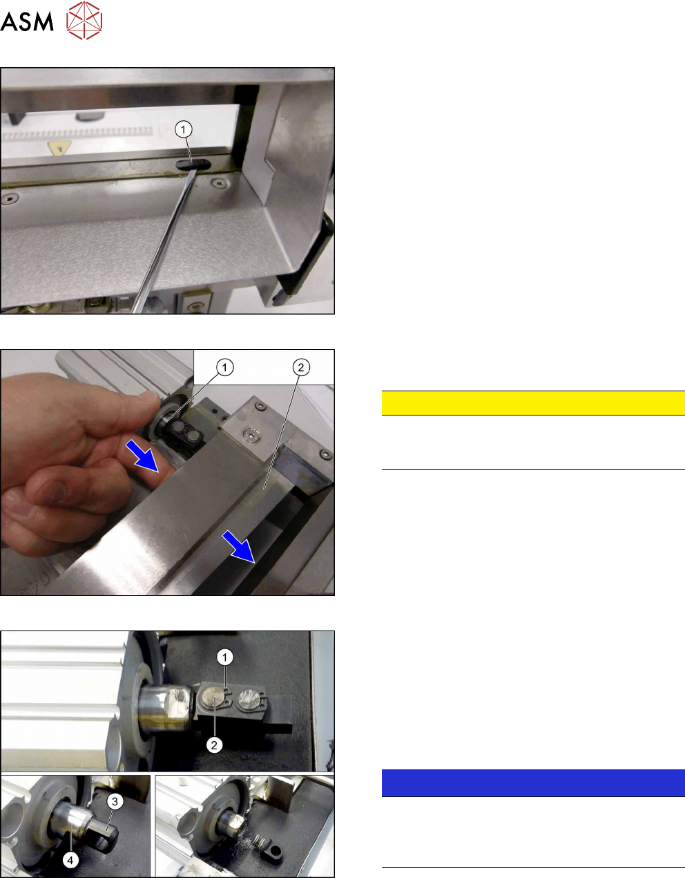
Fig.360: Plastic caps
From the bottom side of the cutter you have easy ac-
cess to the plastic cap.
► Remove the plastic caps(1) over the fastening
screws on both sides of the movable blade.
► Remove the two screws.
Fig.361: Movable blade
► Loosen the movable blade(2) from the piston(1)
of the short-stroke cylinder.
CAUTION!
Risk of injury!
There is a risk of injuring yourself on the cutting
edge of the blades.
.
Fig.362: Removing the articulated joint
► Remove the circlip (1).
► Push the piston rod a little into the short-stroke
cylinder and rotate the articulated joint by 90de-
grees.
► Push the bolt(2) out of the articulated joint.
► Unscrew the remaining articulated joint ad-
apter(3) from the piston(4).
NOTICE!
The adapter is secured with locking varnish
(Loctite no. 243). You will need somewhat more
strength than usual to loosen it.
Hold against it with a spanner wrench.
.