00198150-02_SM_TX_en.pdf - 第62页
3 SMPS 3.12 Replacing the CAN Interface CINX [03108598‑xx] 62 Service Manual SIPLACE TX Series 06/2017
3 SMPS
3.12 Replacing the CAN Interface CINX [03108598‑xx]
Service Manual SIPLACE TX Series 06/2017 61
3.12 Replacing the CAN Interface CINX [03108598‑xx]
Parts, equipment and tools
●
CAN interface CINX [03108598-xx]
Overview
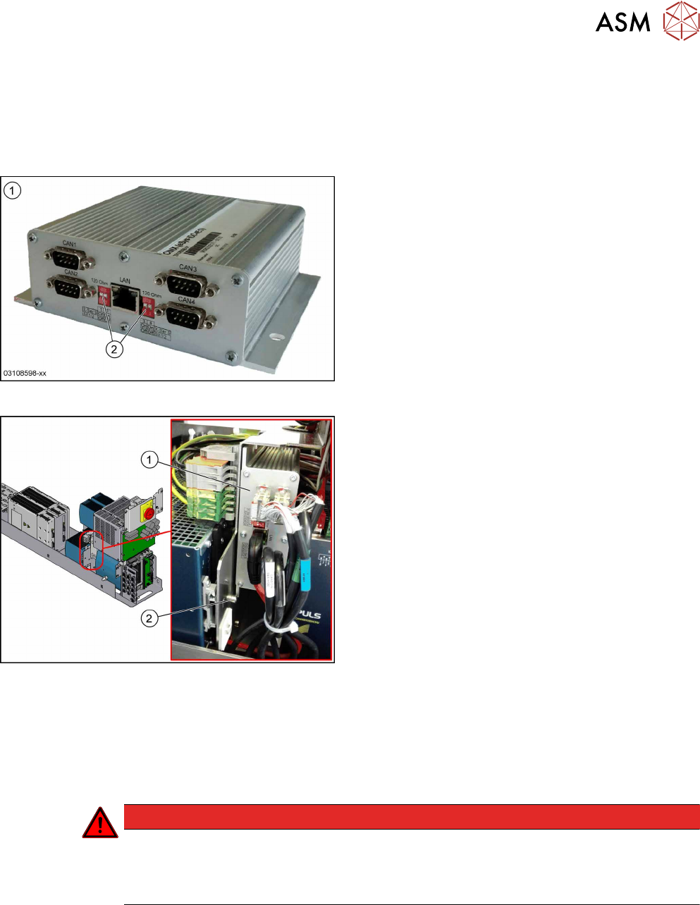
Fig.63: CAN interface CINX
1. CAN interface CINX [03108598-xx]
2. DIP switches
Fig.64: CAN interface CINX on SMPS
1. CAN interface CINX
2. Fastening screw
The CAN interface CINX is located at the side of the
power supply.
Removal
► Switch off the machine, disconnect it from the power supply and secure it to prevent
unauthorized reactivation. Observe the instructions in section 1.2 "Preparatory Work..." [}15].
► Remove the power supply fastening screw and pull out the power supply. For more informa-
tion about this read section 3.2 "Pulling out the Power Supply" [}35].
DANGER
Checking for absence of voltage!
► Before you start working check the power supply for absence of voltage and observe
the waiting times! For more information about this read section 3.4 "Checking For Ab-
sence of Voltage" [}37].
► Remove the screw fastening the CAN interface CINX.
► Unplug all electrical connections (3x CAN bus, 1x network). Mark their positions to make clear
assignment easier later on.
► Take the CAN interface CINX out of the machine.
Installation
► Set the four DIP switches to OFF.
► Follow the removal instructions in reverse order for further installation.

3 SMPS
3.12 Replacing the CAN Interface CINX [03108598‑xx]
62 Service Manual SIPLACE TX Series 06/2017
4 Electrical System and Control
4.1 Electrical System and Control - Overview
Service Manual SIPLACE TX Series 06/2017 63
4 Electrical System and Control
DANGER
Observe User Manual
► Please observe the safety instructions in the user manual for all work!
NOTICE
Observe the detailed circuit diagrams!
For more detailed information refer to the circuit diagrams folder of your machine.
●
Detailed circuit diagrams folder for SIPLACE TX-Series (up to no. 499) [DE+EN: 00197933-
xx]
●
Detailed circuit diagrams folder for SIPLACE TX-Series (from no. 500) [DE+EN: 00198274-xx]
4.1 Electrical System and Control - Overview
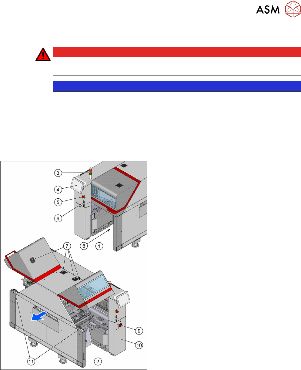
Fig.65: Overview of electrics
1. Location 1
2. Location 2
3. Indicator lamps
4.7 "Indicator Lamps and Illumination" [}72]
4. Monitor
4.5 "Replacing the Monitor [03115169-xx]" [}69]
5. EMERGENCY STOP button
6. Start/Stop buttons
7. Cover fan
4.8 "Replacing the Cover Fan
[03110692-xx]" [}74]
8. Control Computer BoxPC
4.2 "Replacing the Control Computer
BoxPC" [}64]
– 4.3 "Replacing the RAM in the BoxPC" [}67]
– 4.4 "Replacing the GigE Ethernet Ad-
apter" [}68]
9. Main switch
10. Power supply (behind the cover)
11. Cover switch
4.6 "Replacing the Cover Switch
[03110691-xx]" [}70]