SmartSM手册.pdf - 第154页
<O K > Sa v e s the s e t d ata an d clo ses the di a l o g b o x . <Can cel > Sa v e s the s e t d ata an d clo ses the di a l o g b o x . <O u t l in e/ R eal Di splay > Displ a y s th e o u tl i n e …
SM400 User's Manual
画面导言画面导言
[PCB编辑 -元件 ] 脚组 (Align Vision Lead Type (Lead Group) )
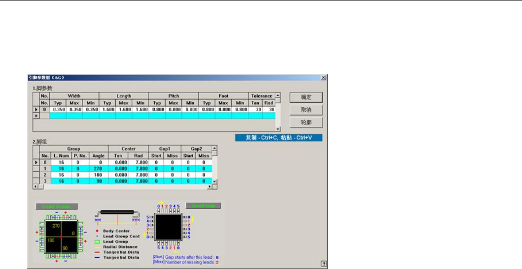
设定User IC 的引脚组。 可设置的Lead Group 最大个数为16个。
菜单项菜单项
<2.<2.脚组>>
评宠弛脠绊
<Group No.>
衮祀脠绊皊缜叽ザ安皊茉固乀0 – 15ザ
<Group L. Num>
设定脚组具有的引线的数量。
<Group P. No.>
设定脚组作参考的引脚参数的编号。可设定的范围为 0 – 7ザ
<Group Angle>
评宠脠绊圮郮哇丐皊斿吗ザ圄丳皊0, 90, 180, 270 衮祀觘庬ザ
<Center Tan>
评宠仔郮哇皊堀凌炿(堀凌炿丆舲昵郮哇皊丳忉)制脠绊皊丳忉皊刍绅斿吗皊跣私ザ
<Center Rad>
评宠仔郮哇皊堀凌炿(堀凌炿丆舲昵郮哇皊丳忉)制脠绊皊丳忉皊泛绅斿吗皊跣私ザ
<Gap1Start>
设定脚组的空位的第一个引线。仔弆姑缜叽皊弛绅皊丑丆丰弛绅弆姑窀体ザ
<Gap1Miss>
评宠脠绊皊窀体皊笲丆丰弛绅ザ与空位值数相等数量的引线空位。
<Gap2 Start>
设定脚组的空位的第二个引线。仔弆姑缜叽皊弛绅皊丑丆丰弛绅弆姑窀体ザ
<Gap2 Miss>
设定脚组的空位的第二个引线。且窀体偂敶盾筏敶釕皊弛绅窀体ザ
<Gap3 Start>
评宠脠绊皊窀体皊笲丏丰弛绅ザ仔弆姑缜叽皊弛绅皊丑丆丰弛绅弆姑窀体ザ
<Gap3 Miss>
设定脚组的空位的第三个引线。
且窀体偂敶盾筏敶釕皊弛绅窀体ザ
<Gap4 Start>
设定脚组的空位的第四个引线。
从开始编号的引线的下一个引线开始空位。
<Gap4 Miss>
设定脚组的空位的第四个引线。与空位值数相等数量的引线空位。

<OK>
Saves the set data and closes the dialog box.
<Cancel>
Saves the set data and closes the dialog box.
<Outline/Real Display >
Displays the outline of the component on the VisFrame window by using the set align
data.
提案事项提案事项
各个引脚组之间不能相互重叠。
脠绊忋颁挍宠1丰脠又敶ザ乥尷昵诺﹦脠绊朏吒粁垑皊弛绅绊或ザ
弛绅台朏仫90庬皊斿吗孞圮
连接项目连接项目
Align Vision User IC
SM400 User's Manual
画面导言画面导言
[PCB编辑 -元件 ] QFP部品的数据设定 ( Align Vision QFP )
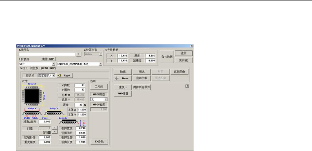
评宠朏兹QFP 郮哇掘初敶捴ザ
菜单项菜单项
为详细的 "1.元件名" , "2. 校正类型" , "3. 封装组" 和 "共同 Data"显示在屏幕顶部,是指 "共同 Data"。
<相机号>
选择识别部品的摄象机。
<Light Control>
评宠诌刱郮哇甮摊豧杀皊煭昔庬ザ
<尺寸>
评宠掘初局対ザ
<X脚数` >
评宠X轺斿吗弛脠皊敶釕ザ
<Y脚数 >
评宠Y轺斿吗弛脠皊敶釕ザ .
<总数 X >
衮祀郮哇圮X轺斿吗皊敺余閅庬ザ妈枢硴宠<朲余X >咒<弛脠閅庬>个丰閅庬﹦仫后讧
皊斿引衮祀ザ( <朲余X > + <弛脠閅庬> * 2)
<总数 Y >
衮祀郮哇圮Y轺斿吗皊敺余閅庬ザ妈枢硴宠<朲余Y>咒<弛脠閅庬>个丰閅庬﹦仫后讧皊
斿引衮祀ザ( <朲余Y> + <弛脠閅庬> * 2)
<误差>
辙八郮仼敶捴皊佟釕ザ堀朲偂乀 30%ザ
<本体X >
评宠郮哇躱皊X轺斿吗皊局対ザ
<本体Y >
评宠郮哇躱皊Y轺斿吗皊局対ザ
<引脚宽度>
设定引线的宽度。
<引脚间距>
设定引脚之间的间距。
<引脚足部>
设定引脚接触到底面的距离。
<引脚长度>
评宠脃煭尊制栧歩 煭僕杀皊弛脠皊閅庬ザ
<选项>
评宠栧歩透顿皊敶捴ザ
<Move>
用于手动吸附部件进行部件识别。
<测试>
侅甮评宠皊Align 敶捴迡衒郮仼诌刱ザ
<抓取图像>
阶段性变换部件形象照明值,保存形象,用户确认其中识别最好的形象照明值进行保存,
帮助指定最佳的照明值。
<自动校正>
臰劮箝刀郮哇掘初敶捴ザ
连接项目连接项目