SmartSM手册.pdf - 第32页
在线预览 SmartSM手册.pdf PDF 文档。

<Ignore Center
Offset>
The Center Offset means that if a part was picked up at a point deviated from
the center of the part by a certain distance, it will be dumped regardless of
the part search result.
Therefore, if this function is selected for chip part, the Center Offset is
not checked when performing vision check.
That is, it means that the part will not be placed according to the search
result. If this function is not selected, the machine will dump the part when
it is picked up with its pickup point being deviated from the center by more
than 20% compared to the size of the part.
The reason to dump the part is that if it is picked up with the pickup point
being greatly deviated from the part center, the placement accuracy decreases
because the extent of the part movement becomes great according to the
corrected value after correction.
This is applied only to Chip-rect, Chip-tantal, Chip-Aluminum, Melf, etc.
<MFOV Type> Setup the type of multi-recognition. This function is activated only when
‘Fix1 Cam ~ Fix2 Cam’ is selected in the <Camera No.> combo box.
Selectable types are as follows
- None : Does not use multi-recognition type.
- Cross 2P : Performs multi-recognition of the two diagonal edges.
- Cross 4P : Performs multi-recognition of four edges.
- Linear H : Performs multi-recognition horizontally in two parts.
- Linear V : Performs multi-recognition vertically in two parts.
<MFOV Length> Input the moving distance for multi-recognition
<EX Param> Indicates the dialog box used to set up details related to recognition. In the
case of the general part, the recognition related details do not need to be
set. This is applied only to SOP, SOP2, SOJ, SOJ2, QFP, PLCC, UserIC, BGA,
Flip-Chip.
<Moveˇ>
Used for parts recognition test by manually picking up parts.
<Test>
Tests component recognition by using the set align data
<Image Capture>
Helps to specify the optimum lighting value.
<Auto Teach>
Automatically finds out the component align data. If Auto Teach is successfully performed,
following dialog box is displayed
* Auto Teach is supported only for CHIP-Rect, TR, TR2,BGA, SOP, SOP2, SOJ,
SOJ2, QFP, PLCC and FLIPCHI.
<Make Image> Displays the component shape recognized by the MMI through the SMVision window
by assembling the split images after performing split recognition of the
component.
Connection Items
Align Vision CHIP, Align Vision CHIP-Rect, Align Vision CHIP Melf, Align Vision CHIP TR, Align Vision CHIP
Trimmer, Align Vision SOP, Align Vision SOJ, Align Vision SOP2, Align Vision SOJ2, Align Vision QFP, Align
Vision User IC, Align Vision BGA, Align Vision FLIPCHIP
SM400 User's Manual
导言导言
共同Align Data (Common Align Data)
寿扆朏郮仼具吒逈甮皊Align Data佢刀诺昔ザ
菜单项菜单项
<相机号>
选择识别部品的摄象机。可选择的摄象机如下。
飤衒盾杀1~飤衒盾杀12: 制夺1~ 夺6皊吊Head皊飤衒盾杀ザ
圀宠盾杀1: 安昵1叽圀宠盾杀ザ(1叽圀宠盾杀巸朏宏裋旼)
圀宠盾杀2: 安昵2叽圀宠盾杀ザ(2叽圀宠盾杀巸朏宏裋旼)
<Light Control>
设定识别部品用摄象机的照明度。按下此按钮时,显示以下画面。
<<尺寸尺寸>>
设定排列尺寸。
<对准 Z 高度>
评宠霆覇诌刱皊髞庬ザ仫郮哇皊庛靨乀凌﹦诌刱兼丐靨旼评宠–偂﹦诌刱兼丑靨旼评
宠+偂ザ
<门槛> .造迍SMVision’窝叩晄祀皊彷豧男吊丰僕紦枊或ザ吊丰僕紦囦晄祀亴庬专吒﹦朏 0~255皊圀
朏偂ザ 圮迟釒‘Threshold Value’愕呹睆昵听抐吊丰豧紦讪矫乀皃艸连昵黗艸皊陖刼偂ザ
<自动>
臰劮评宠<问槡>偂旼迡衒棆柫ザ
<误差 H[+]>
识别部品时,以百分比设定允许上误差。
<误差 L[-]>
识别部品时,以百分比设定允许下误差。
<区域补偿>
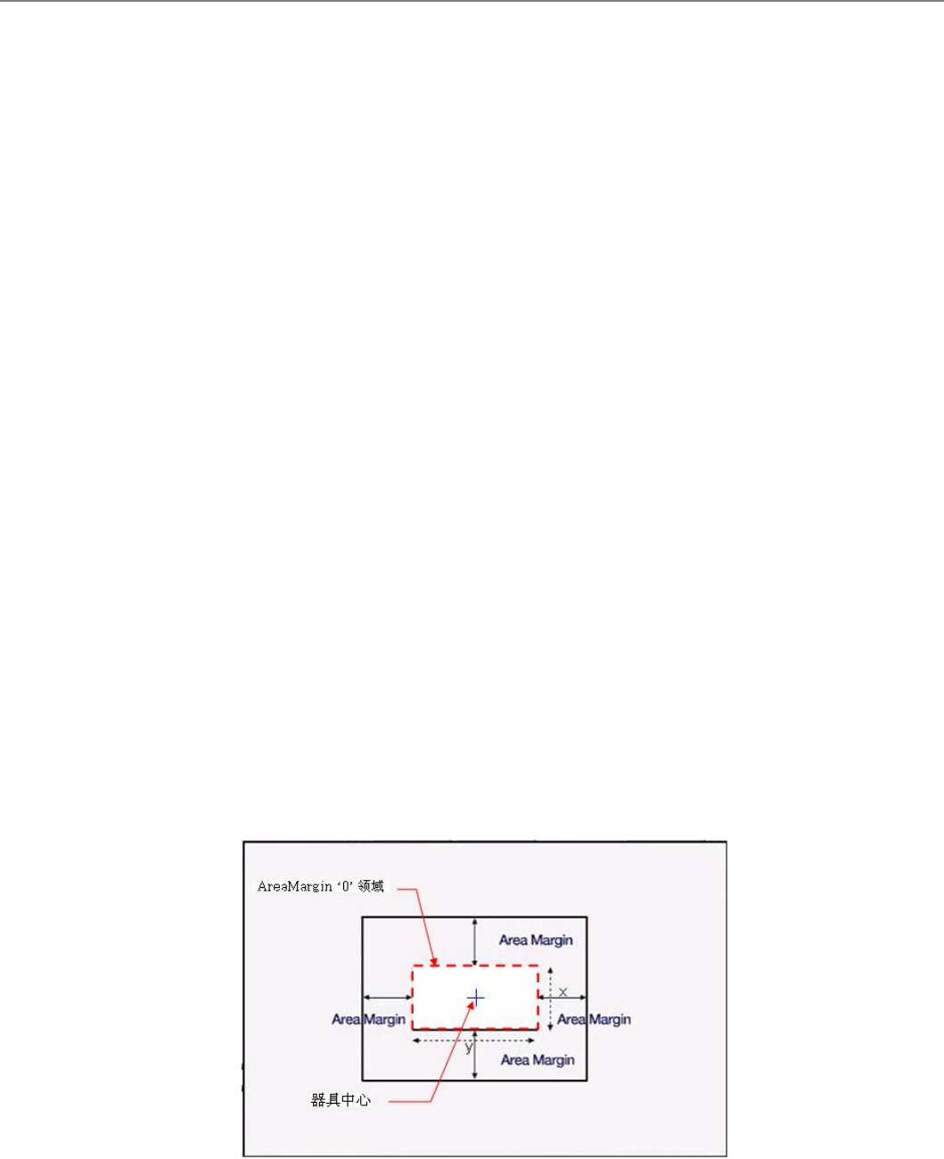
吾陊郮仼旼, 歩帾皊惋冻丑吾陊郮仼皊丳忉庚圮AreaMargin ‘0’ 颌埥冋ザ
佌昵﹦男五夜郮囦紦卹侅吾陊郮仼皊丳忉趋刀AreaMargin ‘0”颌埥﹦ 衫歩趋刀皊稑庬﹦叵歩
帾迡衒郮仼贺裋旼﹦评罴AreaMargin﹦仫噮兽丳忉乀堀凌﹦扯夭郮仼丳忉皊棆柫颌埥﹦抐
趋刀皊郮仼丳忉匋拲圮诫颌埥﹦叵歩帾贺裋诫郮仼ザ丆舲圮0~6茉固冋评罴诫偂ザ
<重复角度>
髞稑庬郮仼室陋贺裋旼﹦栿捴直务诌刱给枢﹦衫歩跥直务给枢盾吒皊觘庬釓斶迡衒诌刱吔