SmartSM手册.pdf - 第29页
S M 4 0 0 U s e r ' s M a n u a l S M 4 0 0 U s e r ' s M a n u a l O v e r v ie w C omm o n Al ig n Data Prov i des details co n cern i n g t h e al i gn data co mm o n l y appl ie d t o al l p art s. M e n u …
SM400 User's Manual
画面导言画面导言
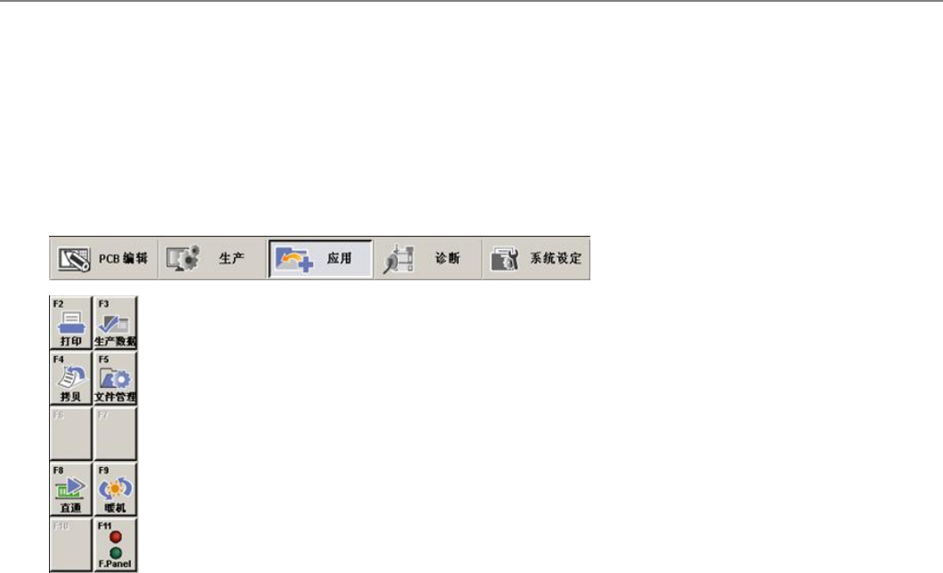
[应用]
庚甮稑底﹢Utility﹣菢卛男Print﹢扙卶﹣﹦Production Information ﹢甥亭俧恵﹣﹦ Copy Between PCB Files ﹢PCB斍
仼乑闺皊拽责﹣﹦File Manager ﹢斍仼箧琌噮﹣﹦Bypass﹢盺造﹣, Warmup ﹢颊烳﹣筏6丰孖菢卛绊或ザ
歪咃仪扭衒统侅甮耋揖価佢丠皊斿俅怭﹦吵劮评复旼揖価朏兹甥亭亭哇皊俧恵皊劥脃ザ
透拯″庚甮※菢卛皊孖菢卛旼﹦诫寿诣桌晄祀圮畁靨丐ザ晄祀孖菢卛盾庚皊寿诣桌皊犼怇丑﹦冓欧透拯菢卛旼诫寿诣桌尌传
夊五流怭匜犼怇ザ
菜单项菜单项
打印 (Print)
扙卶PCB斍仼皊冋宿戜紁绥皊敶捴旼侅甮ザ
生产数据 (Production
Info.)
晄祀朲评复皊吊秓甥亭箧琌朏兹皊俧恵﹢紵讧旼闺﹦贺裋俧恵﹦锟诵俧
恵﹣旼侅甮ザ
拷贝 (Copy)
抐巸朏皊PCB斍仼丐皊敶捴拽责制召丆丰PCB斍仼丐ザ
文件管理 (File Manager)
叵仫迡衒MMI朏兹斍仼皊拽责﹦釓赽吓﹢Rename﹣﹦刦陪﹢Clear﹣筏擓
佢ザ
直通 (ByPass)
辙逇制伦逇裋罴(Conveyor)皊PCB沧朏迡衒贺裋皊犼怇丑盺掫逆刀旼侅甮ザ
预热 (Warm Up)
掫造画準吔﹦扭衒吊驷劮轺皊颊烳ザ
连接项目连接项目

SM400 User's ManualSM400 User's Manual
Overview
Common Align Data
Provides details concerning the align data commonly applied to all parts.
Menu Items
<Camera No.> Select the camera to recognize the component. Available cameras are as follows.
Fly 1 Cam: Fly Camera for Head1.
Fly 2 Cam: Fly Camera for Head2.
Fly 3 Cam: Fly Camera for Head3.
Fly 4 Cam: Fly Camera for Head4.
Fly 5 Cam: Fly Camera for Head5.
Fly 6 Cam: Fly Camera for Head6.
Fix 1 Cam: Fix Camera1. (If Fix Camera1 is installed)
Fix 2 Cam: Fix Camera2. (If Fix Camera2 is installed)
<Light Control> Sets the lighting for the camera to recognize the component.
<Size>
<Align Z> Set the height for recognition. Based on the component surface, if the top is to be
recognized, set - value, and if the bottom is to be recognized, set + value.
<Threshold>
The image viewed through the SM Vision window is composed of each pixel.
Each pixel has a unique value between 0 and 255 according to the seen degree
of brightness. Here, ‘Threshold Value’ indicates the border value deciding
whether each pixel should be recognized in white or black.
<Auto> Check this box to set the <Threshold> value automatically.
<Tolerance H[+]> Set the highest tolerance with a percentage for component recognition.
<Tolerance L[-]>
Set the lowest tolerance with a percentage for component recognition.
<Area Margin>
When the part was picked up, in normal cases, the center of the picked part
must be within the AreaMargin ‘0’ area.
However, when the part can be placed normally by correcting the extent of
deviation even though the center of the picked part was out of the AreaMargin
‘0’ area due to other external cause, the corresponding part can be placed
normally if the deviated center of the part is included in this area by
enlarging the area that checks the part center based on the center of the
mechanism. Generally, set this value to 0~6.
<Repeat Angle>
In the case of the work needed for high precision, this re-recognizes and
pick-up and placement of the component by performing correction according to
the vision recognition result. For example, if o.i is inputted for the repeat
angle, it corrects the angle after vision recognition and re-recognizes it. If
the result of rerecognition is greater than 0.1 it recognizes the angle after
correcting the angle. It repeats this until the result of the recognition
become less than 0.1. When the value becomes 0.1, it pick and place the
component (it tries recognition up to 4 times) Generally this fuction is not
used.
<Option>
<Real Display/Binary> Shows the image seen through the VisFrame in real display to which threshold is not
applied, or in the image (Binary) to which threshold is applied as recognized by MMI.
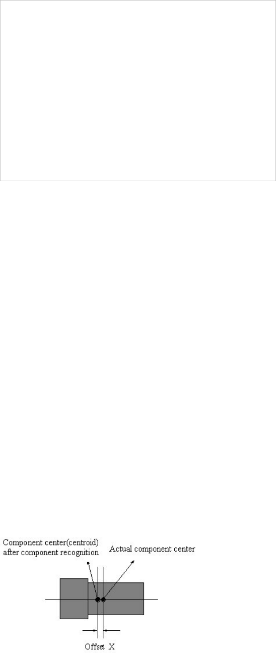
<Offset
<X> edit box
Set the X offset value to be added when the component is placed (After component
recognition, it is the value added after placement point adjustment.) If a component is not
top/down or right/left symmetry and when the component center(centroid) is calculated after
component recognition, it does not coincide with the actual component center. The purpose
of this value is to do regular adjustment by setting the offset value between the obtained
component center(centroid) and the actual component center.
<Y> edit box
Set the Y offset value to be added when the component is placed. (After component
recognition, the value added after component placement point adjustment)
<R> edit box
Set the R offset value to be added when the component is placed.(After component
recognition, it is the value added after component placement point adjustment)