4OM-1208-011_w.pdf - 第106页
1-49 AIVEMT -ID (7) Attach the backup plate to the backup base board so that the chamfered side of the backup plate can be seated toward the central side of the machine. Notice (a) Attach the backup plate so that the cha…
1-48
AIVEMT-ID
4.2 Lubrication for Ball Screw Splines
(1) Zero the conveyors and the heads.
(2) Move the backup base upward.
(3) Turn off the power to the machine.
(4) Open the cover.
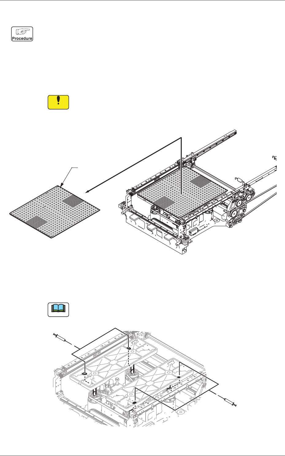
(5) Take out the backup plate.
Notice
If the backup plate collides with a conveyor, etc., the machine will
break down.
Be sure to handle the backup plate carefully.
Backup Plate
Fig. 4A44-1
(6) Apply grease to the ball screw splines of the backup base through
the holes on the backup base with a syringe.
Note
Use No. 19 (brown) nozzle.
Inject grease into
these holes.
Inject grease into
these holes.
Fig. 4A45
0606-009
4.2 Lubrication for Ball Screw Splines
1-49
AIVEMT-ID
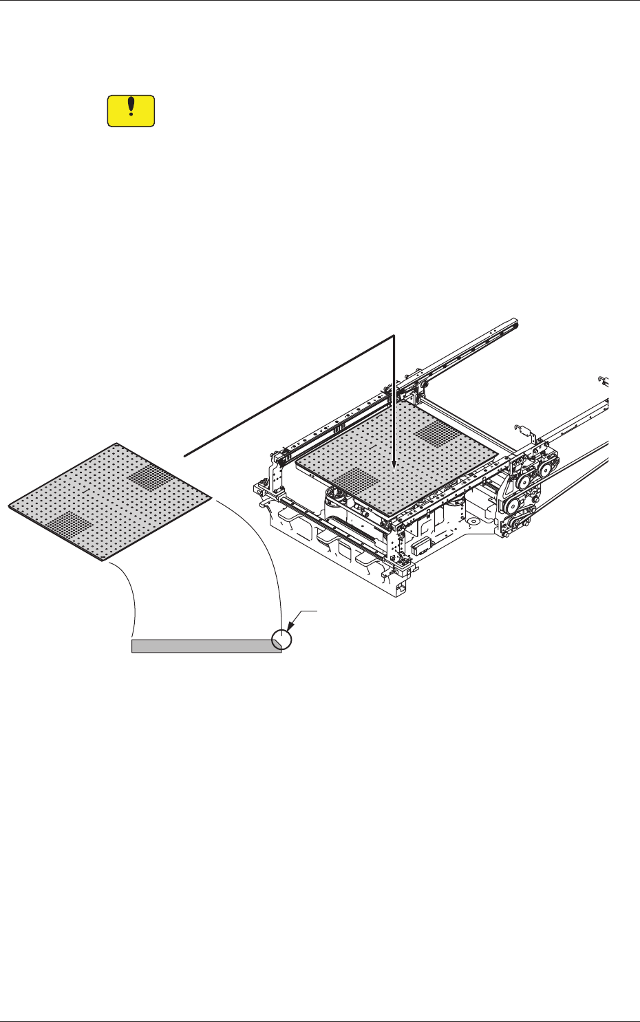
(7) Attach the backup plate to the backup base board so that the
chamfered side of the backup plate can be seated toward the central
side of the machine.
Notice
(a) Attach the backup plate so that the chamfered side can be
seated toward the central side of the machine.
If the plate is not attached correctly, the machine will break
down.
(b) Do not allow any foreign substance to be trapped between
the backup base board and the backup plate. Otherwise, the
machine will break down.
(c) After the backup plate has been attached, confirm that it is
seated firmly without any play, is not tilted, and is directed
correctly.
Set up the backup plate so that the chamfered
side can be seated toward the central side of
the machine.
Chamfered Side
Fig. 4A46
0606-009
4.2 Lubrication for Ball Screw Splines
1-50
AIVEMT-ID
4.3 Replacement of Fluorine Sheet and Urethane Clamp
Time of Replacement
It is recommended that they should be replaced once a year.
Replacement Procedure
(1) Zero the cutter.
Reference
Refer to "4.4 "CUTTER ADJ" Window" in "Chapter 4 (Vol. 2)" for the
zeroing operation of the cutter.
(2) Move down the feeder base and detach the bank feeder change cart.
(3) Turn off the power to the machine.
(4) Open the cover.
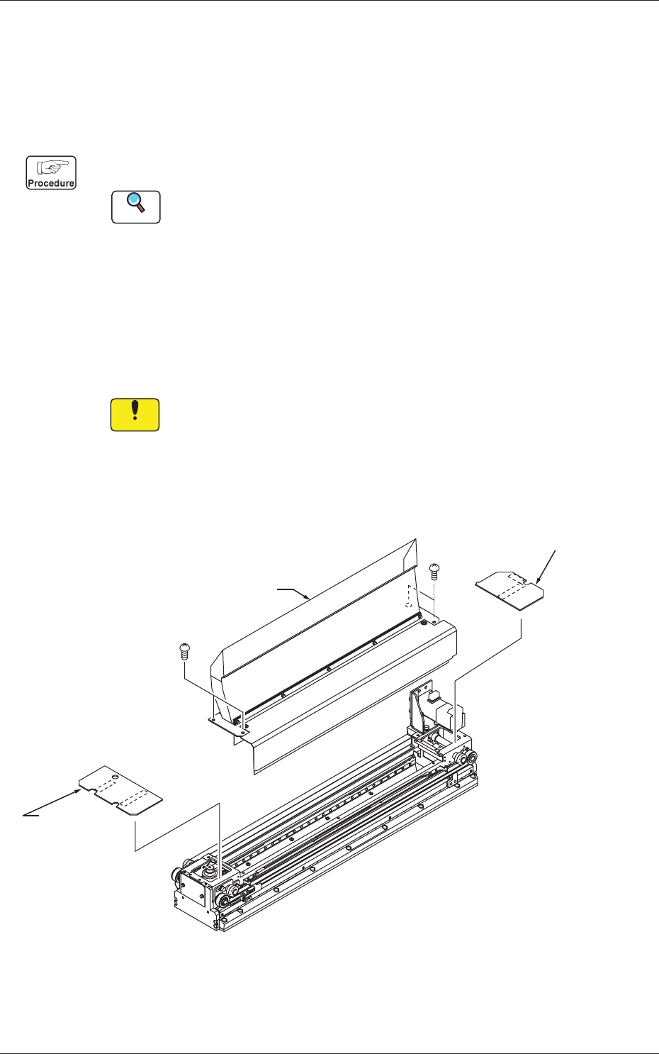
(5) Detach the transparent cover (origin and motor sides) and the tape
guide.
Notice
(a) Carefully detach or attach the tape guide to avoid the Y-axis
linear scale being scratched.
(b) When the cutter is not located at its origin, the tape guide
cannot be detached because the fluorine sheet is caught by the
tape clamp.
Tape Guide
Transparent Cover
(Motor Side)
Transparent Cover
(Origin Side)
Fig. 4A48
0606-009
4.3 Replacement of Fluorine Sheet and Urethane Clamp