4OM-1208-011_w.pdf - 第86页
1-29 AIVEMT -ID W A R N I N G Pay close attention to the cutter blade during the maintenance work. • Lack of attention will result in a hand injury , etc. • Be sure to attach the fixing jig to the cut unit during the main…
1-28
AIVEMT-ID
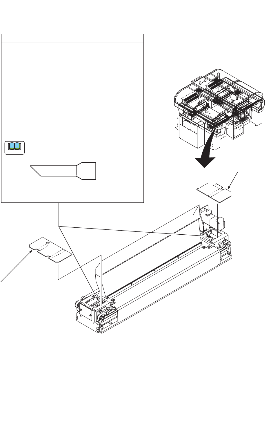
3.3.6 Cutter Section
Transparent Cover
(Motor Side)
Transparent Cover
(Origin Side)
Cutter Boxes (Both Sides)
Every Week Cleaning
(1) Detach the bank feeder change cart.
(2) Move the cutter unit with the [Move Maint. Pos.]
button in the "CUTTER ADJ" window
(the window that opens after the [CUT ADJ]
b
utton on the "UNIT ADJ" submenu bar is pressed).
(3) Turn off the power supply
.
(4) Open the cover.
(5) Detach the transparent covers located on both
sides (origin and motor sides) of the cutter section
and remove dirt and dust with a vacuum cleaner.
Use a vacuum cleaner with a narrow air opening
in the nozzle.
Note
Narrow Air Opening in Nozzle End
(Recommended)
Required Time: 2 minutes
Fig. 4A19-1
0606-009
3.3 Inspection, Cleaning, and Lubrication Spots
1-29
AIVEMT-ID
WARNING
Pay close attention to the cutter blade during the maintenance
work.
•
Lack of attention will result in a hand injury, etc.
•
Be sure to attach the fixing jig to the cut unit during the
maintenance work for safety purposes.
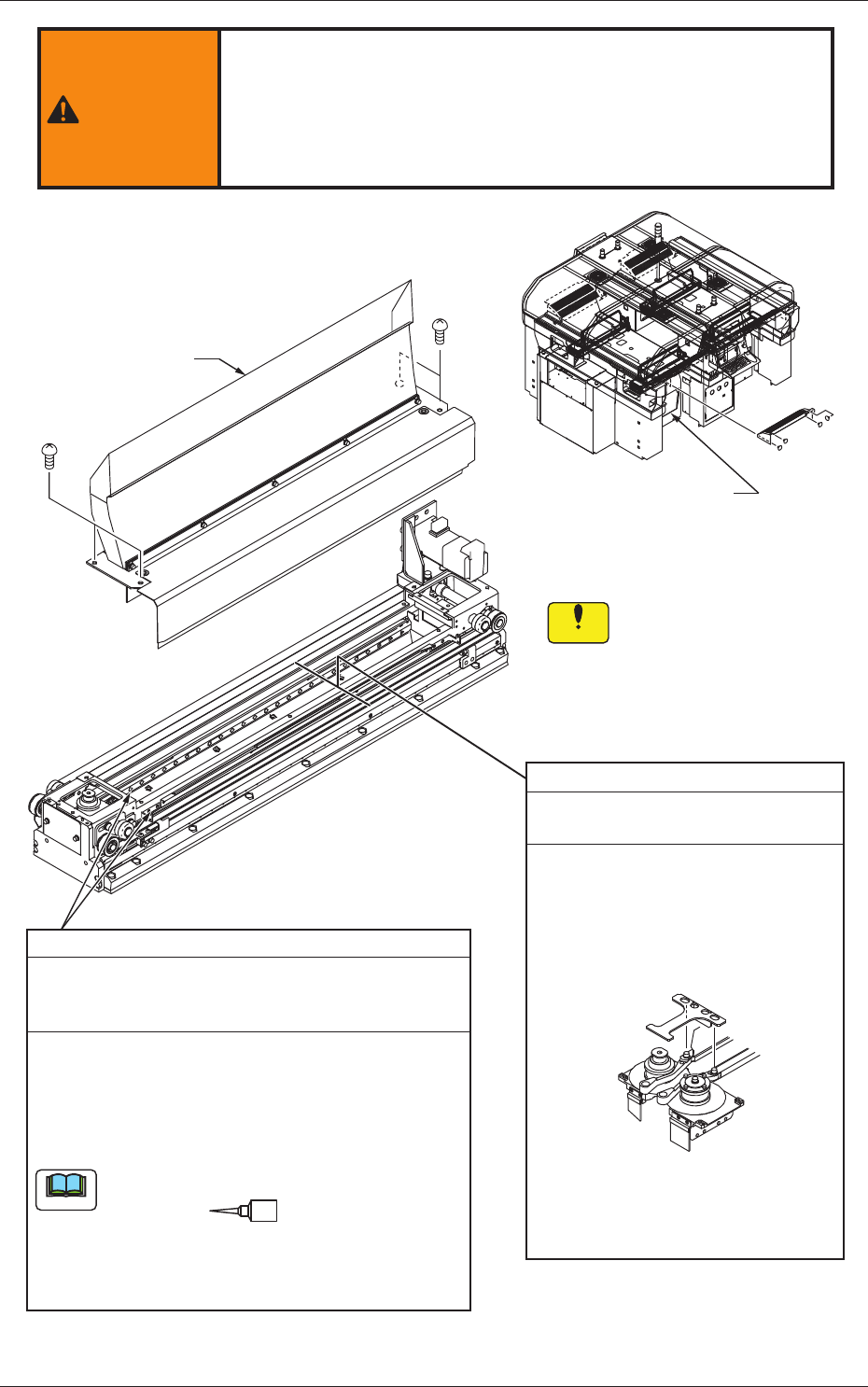
Linear Guides
Every 3 Months Lubrication
(DAPHNE EPONEX GREASE No. 1)
Required Time: 10 minutes
(1) Remove four screws and detach the tape guide.
(2) Wipe off the old grease with a rag and apply a
small amount of new grease to the grooves
(upper and lower ones) of the linear guides with a
syringe.
Use No. 18 (green) nozzle.
As for the low
er groove, put your hand from the cut
waste chute (cover) and apply the grease to the groove.
Tape Guide
Cut Waste Chute (Cover)
When the tape guide is
detached or attached,
be sure to keep the Y-axis
linear scale free of nicks
and scratches.
Notice
Cutter Box
Every 3 Months Cleaning
Required Time: 5 minutes
(1) Remove four screws and detach
the tape guide.
(2) Use the outer hole of the cut unit
fixing jig and attach the jig with
the bent portion being directed
downward.
No. 18
Note
Attachment Position of
Cut Unit Fixing Jig
(3) Clean the area around the linear
guides with a vacuum cleaner.
Fig. 4A19-2
0606-009
3.3 Inspection, Cleaning, and Lubrication Spots
1-30
AIVEMT-ID
WARNING
Pay close attention to the cutter blade during the maintenance
work.
•
Lack of attention will result in a hand injury, etc.
•
Be sure to attach the fixing jig to the cut unit during the
maintenance work for safety purposes.
Attachment Position of
Cut Unit Fixing Jig
Attachment Position of
Cut Unit Fixing Jig
When the tape guide is
detached or attached,
be sure to keep the Y-axis
linear scale free of nicks
and scratches.
Notice
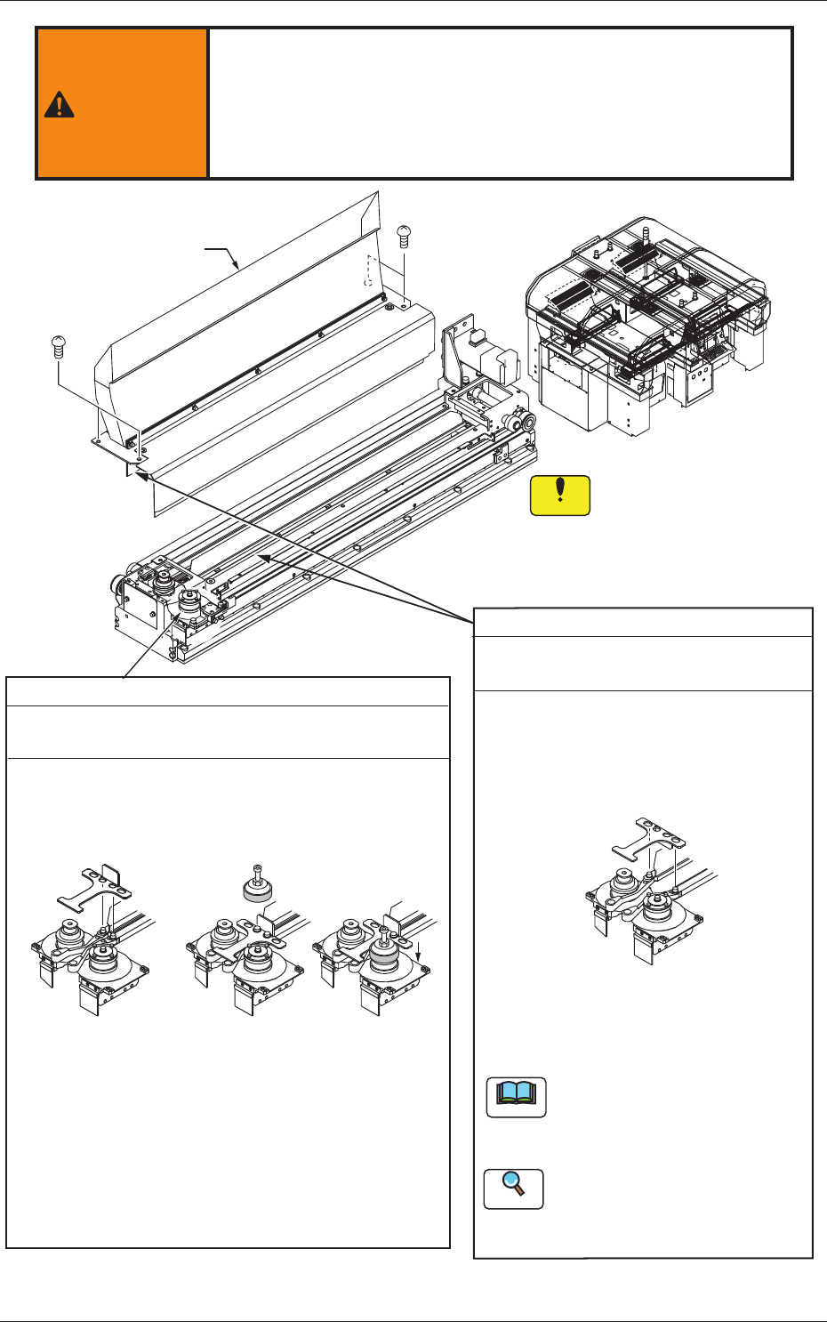
Flat Ring
Every 3 Months Replacement
Required Time: 10 minutes
(1) Remove four screws and detach the tape guide.
(2) Use the inner holes of the cut unit fixing jig with the
tape clamp being closed and attach the jig with the
bent portion being directed upward.
Fluorine Sheet, Urethane Clamp
Ever Year Replacement
Required Time: 5 minutes
(1) Remove four screws and detach
the tape guide.
(2) Use the outer hole of the cut unit
f
ixing jig and attach the jig with the
bent portion being directed downward.
(3) Replace the fluorine sheet and the
urethane clamp.
Refer to "4.3 Replacement of
Fluorine Sheet and Urethane
Clamp" for the replacement
procedure.
Note
After the fluorine sheet has been
replaced, activate the cutter
without a tape and cut the
fluorine sheet.
Reference
Tape Guide
(3) Cut the used flat ring with a cutter on market and
detach it.
(4) Attach a new flat ring to the flat ring replacement jig.
(5) Put the flat ring replacement jig on the roller on the
oscillating side (outside of the machine) and push
down the flat ring until it is inserted into the groove
of the roller.
Replacement Jig
Attached
Fig. 4A19-3
0606-009
3.3 Inspection, Cleaning, and Lubrication Spots