4OM-1208-011_w.pdf - 第74页
1-17 AIVEMT -ID (Front Side of Machine) (Rear Side of Machine) Component Recognition Camera Section Conveyor Section PCB Positioning Section Head Section X/Y Beam Section Nozzle Stocker Section Cutter Section Feeder Base…
1-16
AIVEMT-ID
3. Maintenance Spots
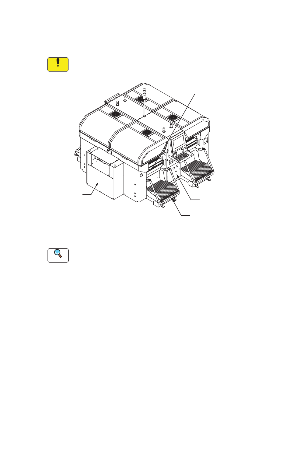
3.1 Whole View
Notice
Any operations with a cover(s) being removed are included.
After the maintenance work, be sure to attach the cover.
Feeder Cart Section
Control Box Section
Air Source
Vacuum System
Fig. 4A6 Front View of Machine
Reference
(a) Refer to "3.3" and the subsequent items for the detailed information
on the spots of each section to be maintained and how to maintain
them.
(b) As for the options, refer to each instruction manual of the specially
specified devices for the maintenance.
0606-009
3. Maintenance Spots
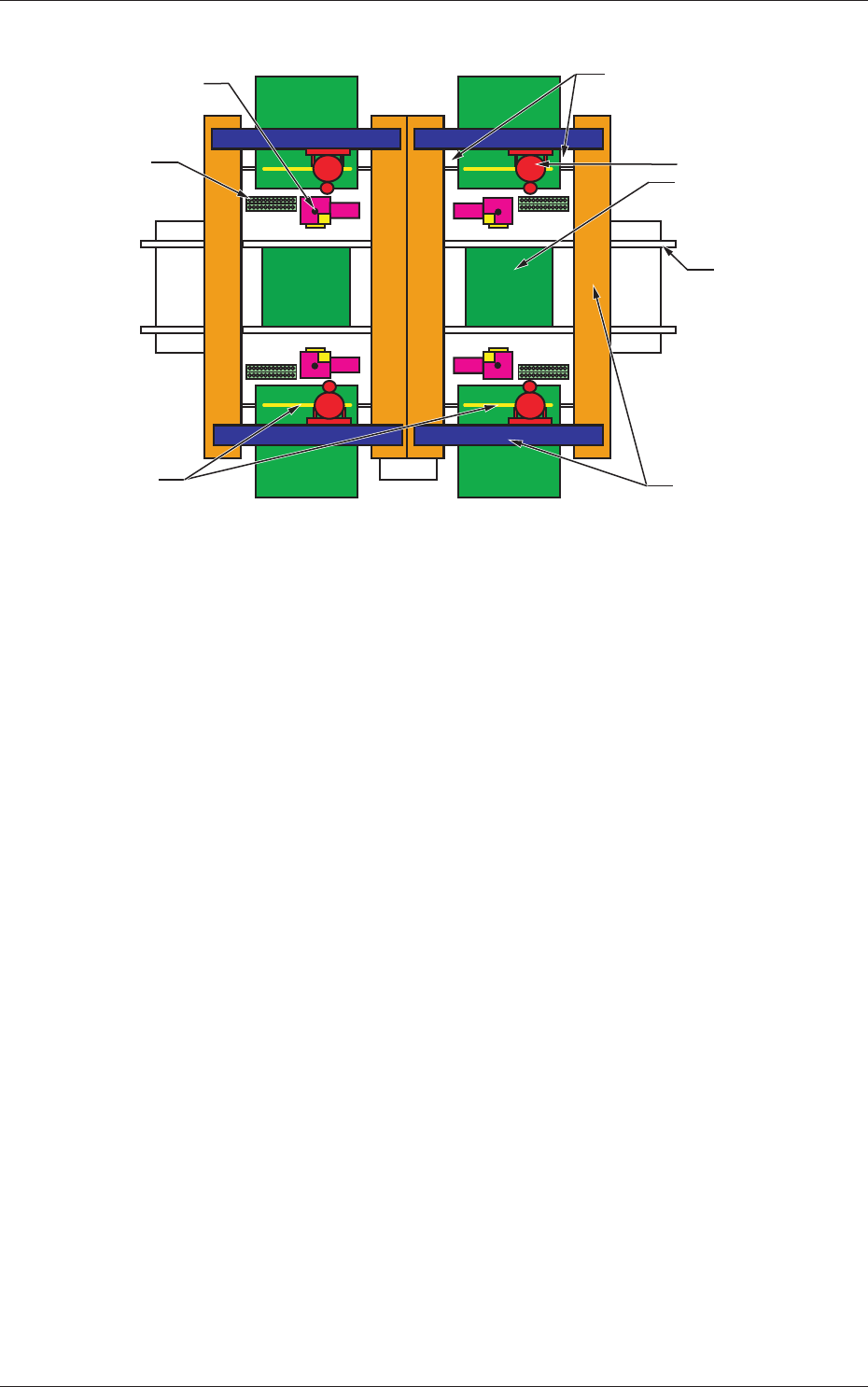
1-17
AIVEMT-ID
(Front Side of Machine)
(Rear Side of Machine)
Component Recognition
Camera Section
Conveyor Section
PCB Positioning
Section
Head Section
X/Y Beam Section
Nozzle Stocker
Section
Cutter Section
Feeder Base Driving Section
Fig. 4A8
0606-009
3.1 Whole View
1-18
AIVEMT-ID
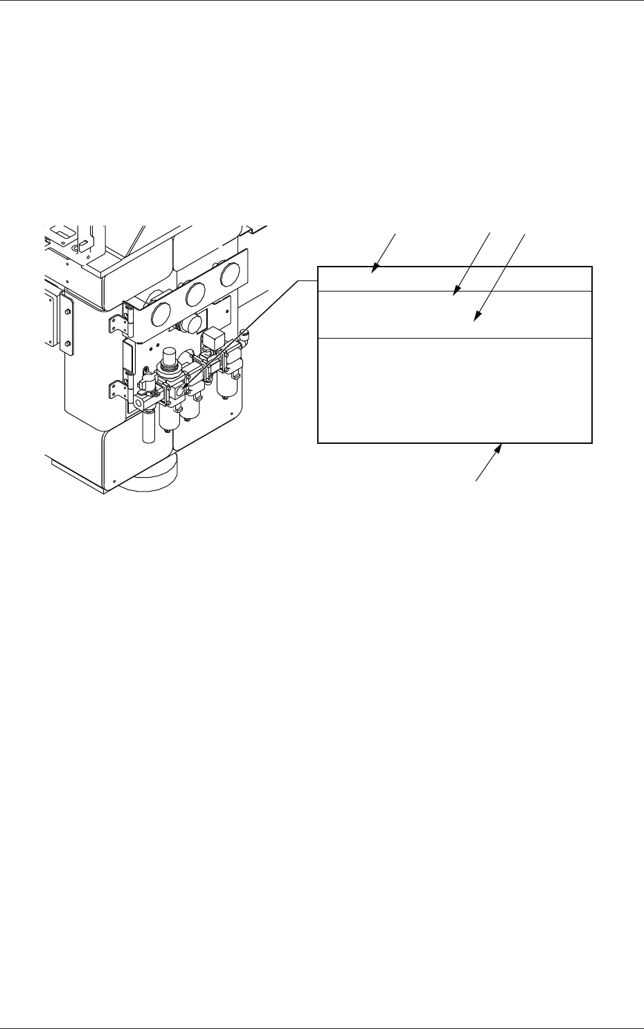
3.2 Understanding of Maintenance Items on Each
Section
The following describes how to view the description of each field (numbered
fields) in "3.3 Inspection, Cleaning, and Lubrication Spots".
View of Inspection, Cleaning, and Lubrication Spots
(Example of Identification)
Main Air Pressure
Every Day Inspection
Required Time: 1 minute
Set Air Pressure 0.45 MPa (4.6 kgf/cm
2
)
Check to see that the air pressure is
Min. 0.4 MPa (4.1 kgf/cm
2
) while the
machine is running.
If not, adjust the air pressure.
[1]
[2]
[4]
[3]
Fig. 4A9
[1]:
Maintenance Spot
[2]:
Cycle and Contents of Maintenance
[3]:
Details of Maintenance
[4]:
Approximate Time required for the Maintenance
(excluding the time required to detach or attach the cover, etc.)
0606-009
3.2 Understanding of Maintenance Items on Each Section