00900194-01_SM_ASM ProcessLens_Dual-lane_EN.pdf - 第16页
2 General 16 Service Manual ASM ProcessLens Dual-lane 09/2018
2 General
Service Manual ASM ProcessLens Dual-lane 09/2018 15
2 General
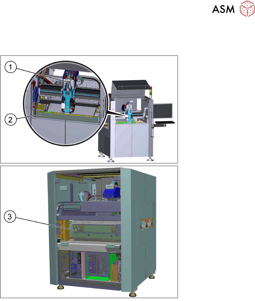
Machine overview
1. Optical head
2. Front Conveyor
3. Motor for the width
adjustment
The ASM ProcessLens is an inline solder paste inspection machine which visually inspects 100%
of paste deposits on any given product in 3D and 2D and compares them to their expected volume,
X and Y position, area, mean height and shape.
It also checks for bridging between adjacent pads and coplanarity failures for a group of pads be-
longing to the same component.
This visual control is based on the stencil's Gerber data which contains all the apertures, their
shape, size, orientation and position as well as the stencil thickness.
The ASM ProcessLens saves all measurement data on its hard drive. ASM ProcessLens also
measures the warpage of each PCB during the inspection and uses this data to keep the images in
sharp focus by adjusting the height of the Z-axis accordingly. The evolution and history of the print-
ing process can be visualized through the SPC (Statistical Process Control) package delivered with
the machine.
ASM ProcessLens together with ASM ProcessEngine is a product called ASM ProcessExpert
which provides monitoring, analyzing, correcting and improving the printing process automatically.
For detailed information about the ASM ProcessLens solder inspection machine see also the oper-
ating manual.

2 General
16 Service Manual ASM ProcessLens Dual-lane 09/2018
3 Replacing spare parts
3.1 Optical head
Service Manual ASM ProcessLens Dual-lane 09/2018 17
3 Replacing spare parts
3.1 Optical head
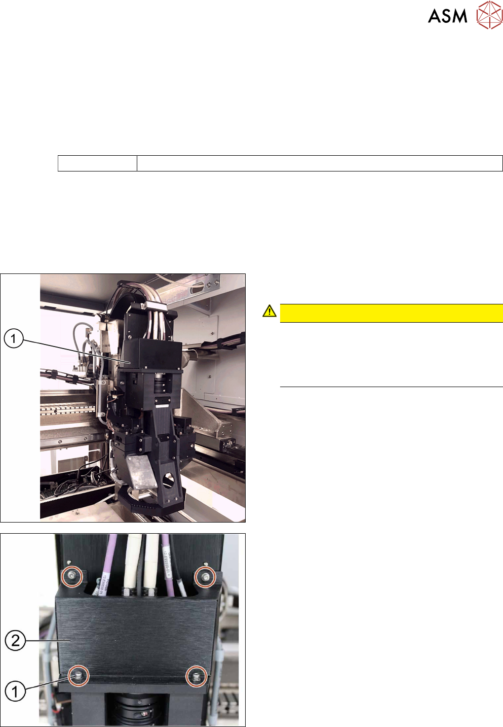
3.1.1 Replacing the optical head
Parts
03122959-xx Vision module
Equipment and tools
●
Allen key size 2.5
Requirements
●
Machine is switched off.
Removal
► Move the optical head(1) carefully to the middle
of the machine.
CAUTION!
Sensitive camera system
The camera system is very sensitive and must
therefore not be touched.
Make sure you don’t touch the camera when
moving the gantry.
.
► Remove the cover(2) that protects the connec-
tion spots for the cables by unscrewing the
screws(1) by using an Allen key size 2.5.
► Place the dismantled cover on a service table.