00900194-01_SM_ASM ProcessLens_Dual-lane_EN.pdf - 第82页
4 Replacing spare parts at the conveyor 4.6 Fiber optic cables and laser light barriers 82 Service Manual ASM ProcessLens Dual-lane 09/2018 4.6.4 Replacing the fiber optic sensor Parts Fig.65: Fiber optic sensor 0309329…
4 Replacing spare parts at the conveyor
4.6 Fiber optic cables and laser light barriers
Service Manual ASM ProcessLens Dual-lane 09/2018 81
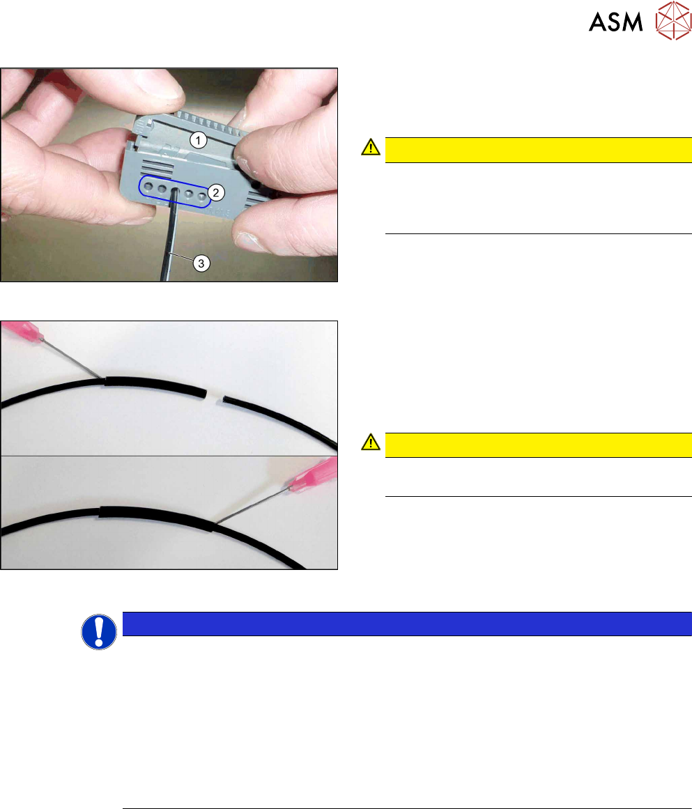
Fig.63: Cutter tool
1. Cutter tool
2. Cutting aperture
3. Fiber optic cable
CAUTION!
Only use each cutting aperture once
Make sure that you only use each cutting aper-
ture once. If they are used more than once, good
quality cuts can not be guaranteed.
.
Fig.64: Repairing the fiber optic cables
► Slide both ends of the fiber optic cable into the
repair hose until they touch each other.
► Use Loctite 406 on the repair hose.
Thus, the fiber optic cable is fixed in the hose.
The two ends of the fiber optic cable are not
glued to each other.
CAUTION!
Highly viscous instant glue
Use gloves and a dosage tip.
.
NOTICE
Installation instructions
► Check the setting for the transmitter / receiver and correct it if necessary (see Setting
and Correcting the Laser Light Barrier).
► Calibrate the sensors of the PCB conveyor.
► Check the display on the fiber optic sensor. The displayed value must be above 100.
Check the value for different conveyor widths (red = output / green = input).
► Mark the optical system and the fiber optic cable at the fiber optic sensor with the glue
dot supplied. The glue dot indicates that the fiber optic cable has already been re-
paired and that a replacement is compulsory at the next defect.
4 Replacing spare parts at the conveyor
4.6 Fiber optic cables and laser light barriers
82 Service Manual ASM ProcessLens Dual-lane 09/2018
4.6.4 Replacing the fiber optic sensor
Parts
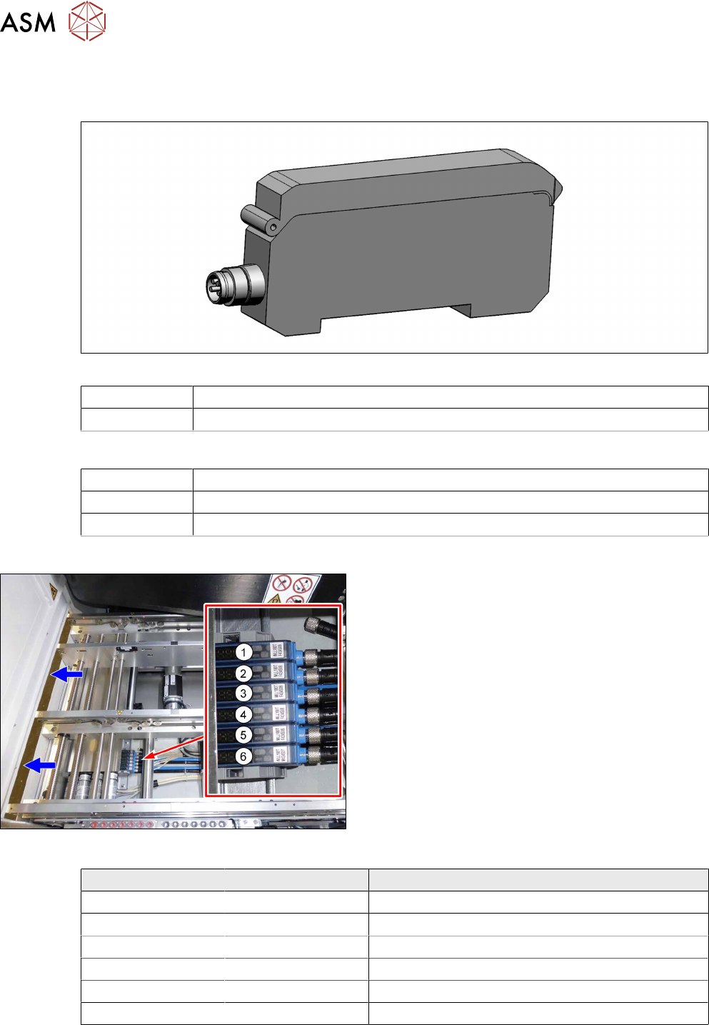
Fig.65: Fiber optic sensor
03093294-xx Fiber optic sensor WLL180T-M pre-programmed SXa (master)
03093295-xx Fiber optic sensor WLL180T-F pre-programmed SXa (slave)
Equipment and tools
00353832-xx Allen key set
Side cutter
Cable ties
Overview
Fig.66: Fiber optic sensors
The fiber optic sensors are located at location 2 under
the lifting table plate.
(1) to (6): fiber optic sensors for the input area, place-
ment area and output area.
The receivers are always at the top of the fiber optic
sensors and the transmitters at the bottom.
Conveyor track Designation Description
Track 1 1 (slave) Output area
2 (slave) Placement area
3 (slave) Input area
Track 2 4 (slave) Output area
5 (slave) Placement area
6 (master) Input area
4 Replacing spare parts at the conveyor
4.6 Fiber optic cables and laser light barriers
Service Manual ASM ProcessLens Dual-lane 09/2018 83
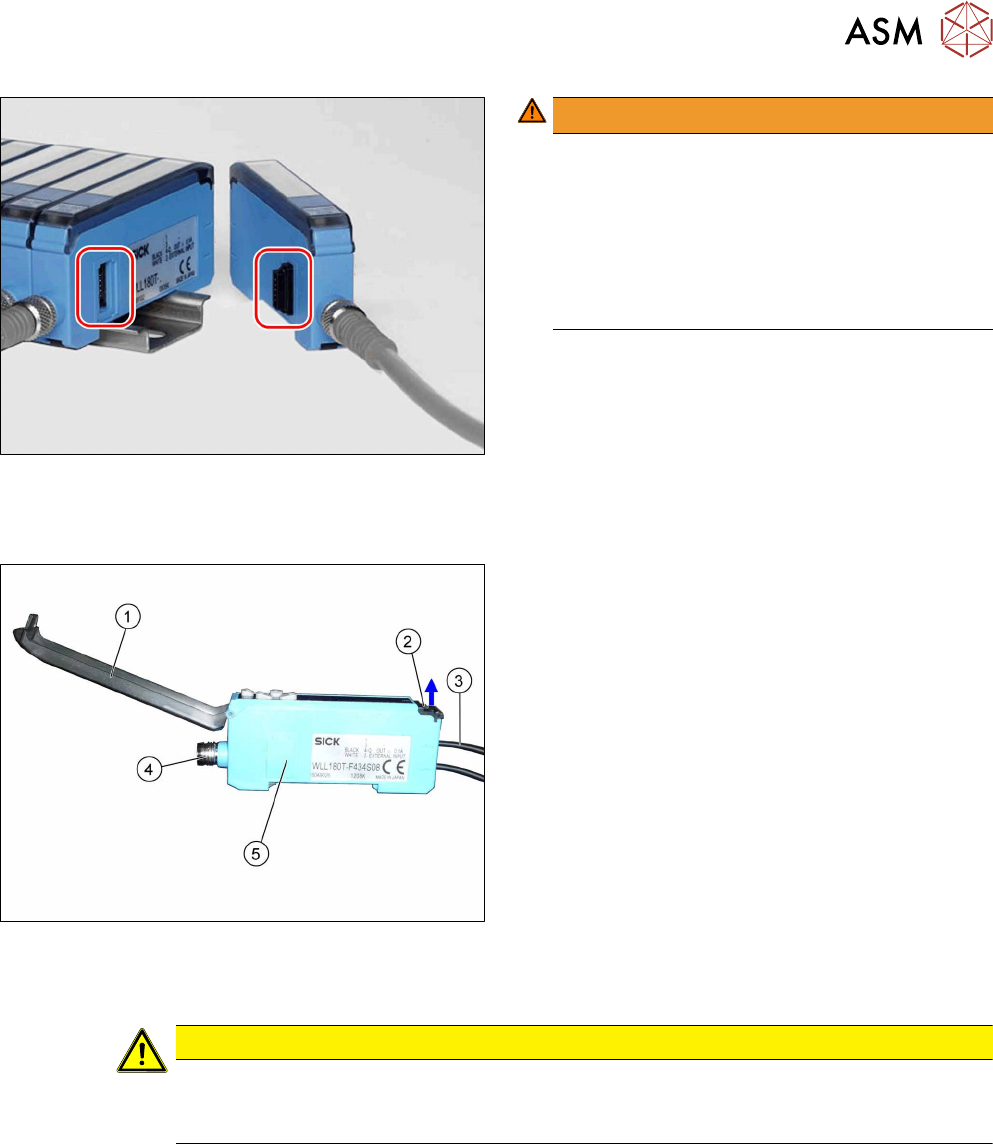
Fig.67: Plug-and-socket connections
WARNING!
The adjacent fiber optic sensors are connec-
ted via plug-and-socket connections on the
side.
Before dismantling the fiber optic sensors always
separate them a bit.
Do not lift the fiber optic sensors off without sep-
arating them first. If you do so, you may damage
the plug-and-socket connection.
.
Each sensor has two fiber optic cables connected (transmitter/receiver), which belong to the same
conveyor belt (segment).
Fig.68: Fiber optic sensor
1. Cover
2. Locking the fiber optic cables
top = open
bottom = closed
3. Fiber optic cable
Top: input (from receiver)
Bottom: output (to transmitter)
4. Electrical connection
5. Electrical connection to neighboring fiber optic
sensor (under the plastic cover)
Removal
CAUTION
Do not bend fiber optic cables
► Make sure you do not bend the fiber optic cables. Otherwise the cable will become
cloudy and no longer transmit the signal properly.
► Use the software or manually move the conveyor rail into a position which allows you best
access.
– To move the conveyor rail manually, pull the toothed belt of the width adjustment unit.
► Switch off the machine, disconnect it from the power supply and secure it to prevent
unauthorized reactivation.