00900194-01_SM_ASM ProcessLens_Dual-lane_EN.pdf - 第85页
4 Replacing spare parts at the conveyor 4.6 Fiber optic cables and laser light barriers Service Manual ASM ProcessLens Dual-lane 09/2018 85 Installation ► Follow the removal instructions in reverse order for installation…
4 Replacing spare parts at the conveyor
4.6 Fiber optic cables and laser light barriers
84 Service Manual ASM ProcessLens Dual-lane 09/2018
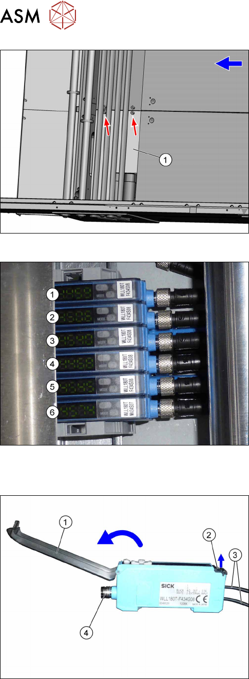
Fig.69: Cover
► Remove the two screws fastening the cover(1)
and remove the cover.
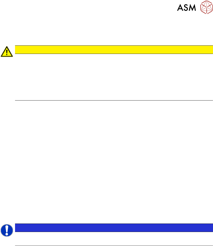
Fig.70: Fiber optic sensors
The individual fiber optic sensors are connected to
one another via a small terminal strip.
Dismantle the fiber optic sensors one after one begin-
ning with (6) (track2) until you have reached the fiber
optic sensor to be replaced. Perform the following
tasks at each fiber optic sensor:
Dismantling a fibre optic sensor
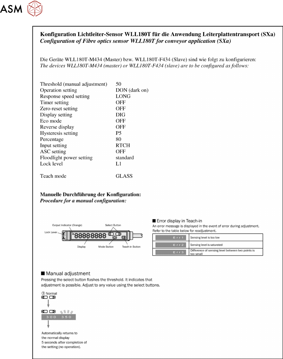
Fig.71: Fiber optic sensor
► Open the cover(1) on the fiber optic sensor.
► Open the lock(2) on the fiber optic cables(3) and
then pull off the fiber optic cables. You might like
to mark their positions to make clear assignment
easier later on.
► Disconnect from the power supply(4). You may
want to mark the position, to make clear assign-
ment easier later on.
► Pull the fiber optic sensor slightly away from the other fiber optic sensors, to loosen the elec-
trical connection to the neighboring fiber optic sensor.
Now you can pull the sensor up and off the strip.
► Repeat these steps if needed for any other fiber optic sensors.
4 Replacing spare parts at the conveyor
4.6 Fiber optic cables and laser light barriers
Service Manual ASM ProcessLens Dual-lane 09/2018 85
Installation
► Follow the removal instructions in reverse order for installation. Also observe the following
instructions:
CAUTION
Installation instructions
► On the fiber optic sensor, remove the plastic cover above the side plug-and-socket
connections, if needed.
► Check the setting on the fiber optic sensor and correct if necessary (see following sec-
tion).
New fiber optic sensors are preset.
► Teach the PCB sensors.
4.6.4.1 Setting the fiber optic sensor
The brightness of the sensors changes according to the positions of the conveyor rails. For this
reason, the sensors are automatically recalibrated after each automatic adjustment of the conveyor
rails.
If the conveyor rails are manually adjusted, there will be no automatic calibration. In this case, cali-
bration needs to be manually triggered in the Service menu. Without this calibration, the station
software will show boards which are not physically present.
You can check the correct calibration on the sensor modules.
●
Red display: current signal strength of receiver
●
Green display: reference value of receiver
A board is recognized if the value in the red display is smaller than the value in the green display.
Without a board, the value of the green display must be 10 to 20% smaller than the value of the
red display.
During calibration, the reference value (green display) is automatically set to a lower value than the
current signal strength (red display). It is assumed that there is no board in the sensor range at this
moment.
The absolute sensor value is not significant. This can vary between sensor modules.
NOTICE
No board in conveyor
When calibrating the light barriers make sure that there is no board in the conveyor.
4 Replacing spare parts at the conveyor
4.6 Fiber optic cables and laser light barriers
86 Service Manual ASM ProcessLens Dual-lane 09/2018
Fig.72: Setting the fiber optic sensor - 1