00900194-01_SM_ASM ProcessLens_Dual-lane_EN.pdf - 第44页
4 Replacing spare parts at the conveyor 4.2 Lifting table 44 Service Manual ASM ProcessLens Dual-lane 09/2018 Fig.18: Motor crank and brackets The motor crank (4) and the brackets (2) need to be removed and refitted o…
4 Replacing spare parts at the conveyor
4.2 Lifting table
Service Manual ASM ProcessLens Dual-lane 09/2018 43
Removal
CAUTION
Washers
There are washers at various points, for example between the lifting table motor and the
rods.
► Make a note of the number of washers and their positions. These will need to be fitted
again in the same places later on.
► Use the software or manually move the conveyor rail into a position which allows you best
access.
– To move the conveyor rail manually, pull the toothed belt of the width adjustment unit.
► Switch off the machine, disconnect it from the power supply and secure it to prevent
unauthorized reactivation.
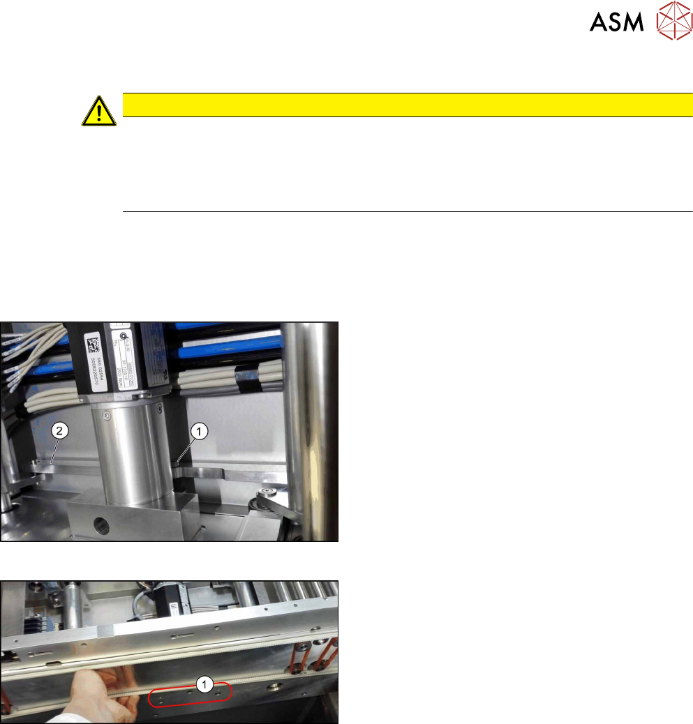
Fig.16: Lifting table motor
► Dismantle the lifting table plate.
4.2.1 "Replacing the lifting table plate" [}38]
► Remove the screw(1) fastening the rods(2).
Carefully dismount the rods.
Fig.17: Fastening screws
► Remove the three screws(1) fastening the retain-
ing bracket.
► Dismantle the cover over the conveyor control board.
► Unthread the cable up to the conveyor control and then unplug it at connection X10. You may
want to mark the position to make clear assignment easier later on.
See also: 4.7.1.1 "Conveyor control TSP420 [03087642-xx]" [}94]
► Remove the lifting table motor from the machine.
4 Replacing spare parts at the conveyor
4.2 Lifting table
44 Service Manual ASM ProcessLens Dual-lane 09/2018
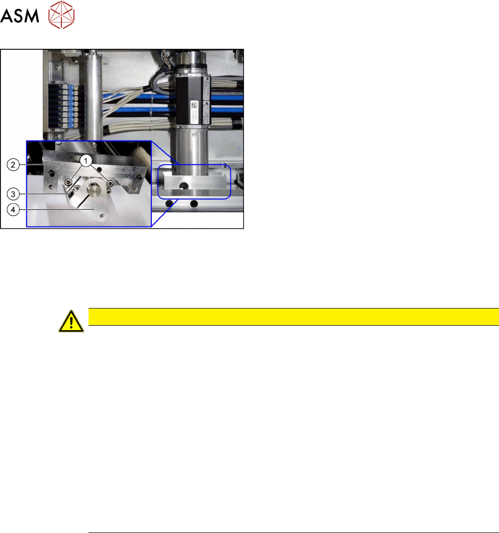
Fig.18: Motor crank and brackets
The motor crank(4) and the brackets(2) need to be
removed and refitted on the new lifting table motor.
► Remove the two screws(1) fastening the brack-
ets(2).
► Remove the screw(3) fastening the motor
crank(4).
Installation
► Follow the removal instructions in reverse order for installation. Also observe the following
instructions:
CAUTION
Installation instructions
► The motor crank and the brackets need to be removed and refitted on the new lifting
table motor.
Use the old lifting table motor as a reference.
Observe the position and number of washers used.
► Tighten the clamping screw on the motor crank.
► Make sure that the motor connection cables do not rub against any parts.
► Place the lifting table plate onto the guidance pins. Make sure that the fastening
screws slide properly into the precut thread.
► Check the free movement of the lifting table (see Checking free movement of lifting
table).
► Calibrate the lifting table motor and then perform a reference run (see Calibrating the
Conveyor Functions).
► For more information about the conveyor control refer to section 4.7.1.1 "Conveyor
control TSP420 [03087642-xx]" [}94].
4 Replacing spare parts at the conveyor
4.2 Lifting table
Service Manual ASM ProcessLens Dual-lane 09/2018 45
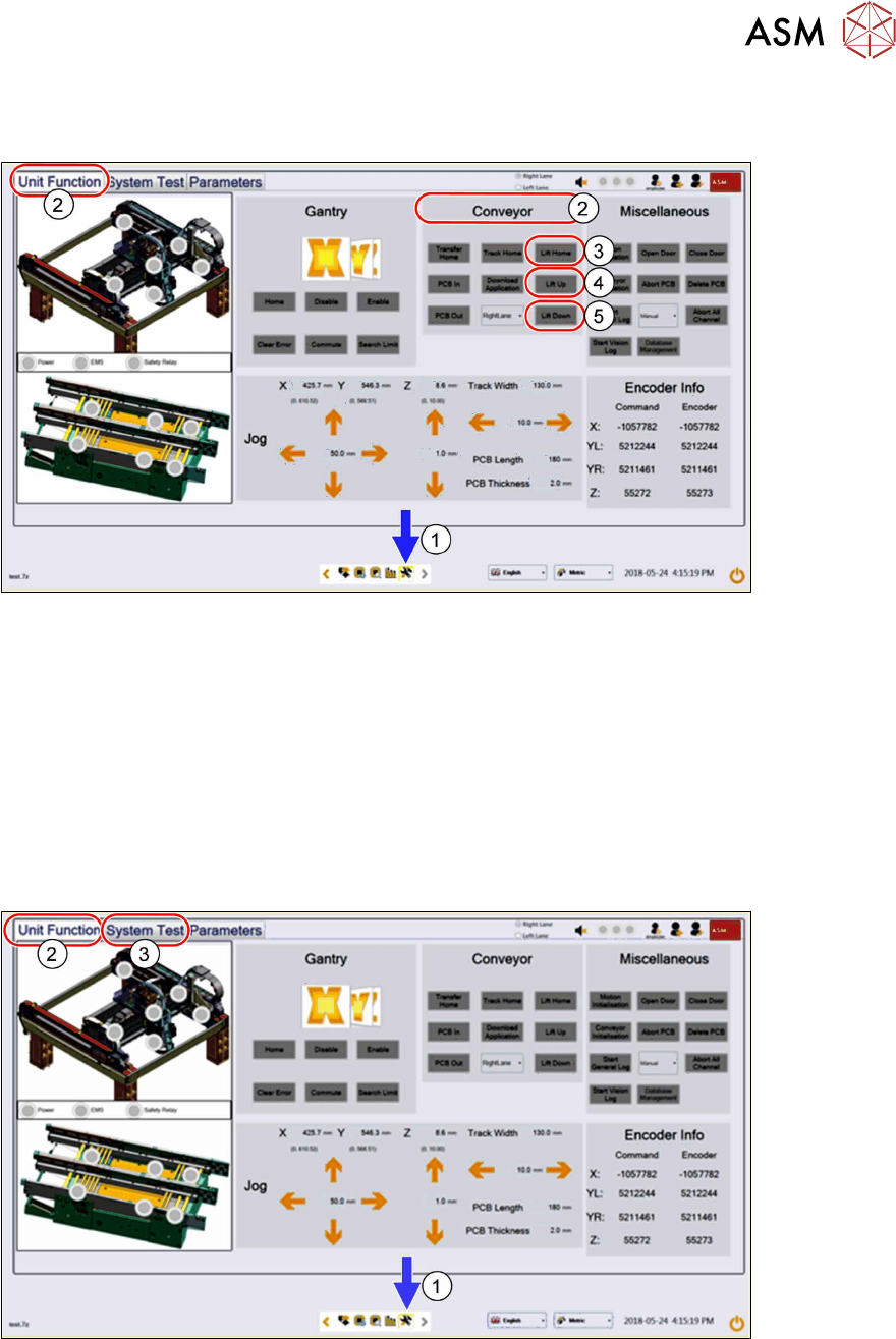
4.2.4 Checking free movement of lifting table
After all work on the lifting table mechanics check the free movement of the lifting table.
► Click on this icon(1) to enter the settings menu.
► Click on Unit Function(2) to enter the settings user menu.
► Switch to the operator level Machine service or better.
► In the Conveyor aera click on Lift Home(3) to move the lifting table to the home position.
► Click on Lift up(4) and Lift Down(5) to ensure all lifting mechanical parts are not obstructed
or there are any assembly issues.
4.2.5 Calibrating the lifting table motor
After completing the work on the lifting table, this will need to be calibrated.
Procedure
► Click on this icon(1) to enter the settings menu.
► Click on Unit Function(2) to enter the settings user menu.
► Switch to operator level Machine service.
► Click on System Test(3) to enter the calibration menu.